LCD with power saving features

a technology of power saving features and display devices, applied in static indicating devices, non-linear optics, instruments, etc., can solve the problems of difficult reading, large electrical consumption, and inability to find wide spread use of reflective displays in portable computers or other devices, so as to reduce the amount of electrical power consumed

Inactive Publication Date: 2006-09-19
MICROSOFT TECH LICENSING LLC
View PDF10 Cites 69 Cited by
  • Summary
  • Abstract
  • Description
  • Claims
  • Application Information

AI Technical Summary

Benefits of technology

The patent is about methods and devices that can save power when using display devices, such as LCDs. The technical effect is to reduce the amount of electricity consumed by these devices.

Problems solved by technology

The technical problem addressed in this patent text is the need for improved displays that can be viewed easily in a wide range of light conditions, without the power consumption associated with backlights. The text discusses various types of LCD displays and their power consumption requirements, and highlights the difficulties in reading displays in direct sunlight or in low light conditions. The patent aims to provide methods and apparatus to reduce power consumption and allow for automated adjustments to brightness settings, without sacrificing display quality or requiring large batteries.

Method used


Image

  • LCD with power saving features
  • LCD with power saving features
  • LCD with power saving features

Examples


Embodiment Construction

[0036]As discussed above, the present invention is directed to methods and apparatus for reducing the amount of electrical power required by display devices, e.g., LCDs.

[0037]In the description which follows, for the purposes of brevity, elements which are the same as, or similar to one another, will be identified using the same reference numerals. In addition, arrows will be used to illustrate rays of light which may be emitted by, e.g., a natural or artificial light source.

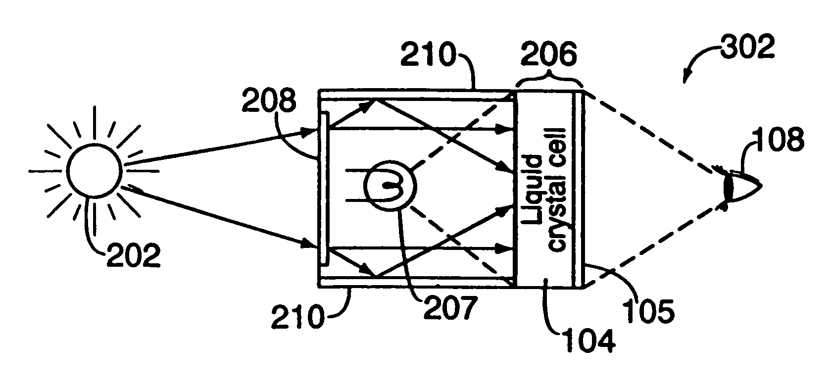
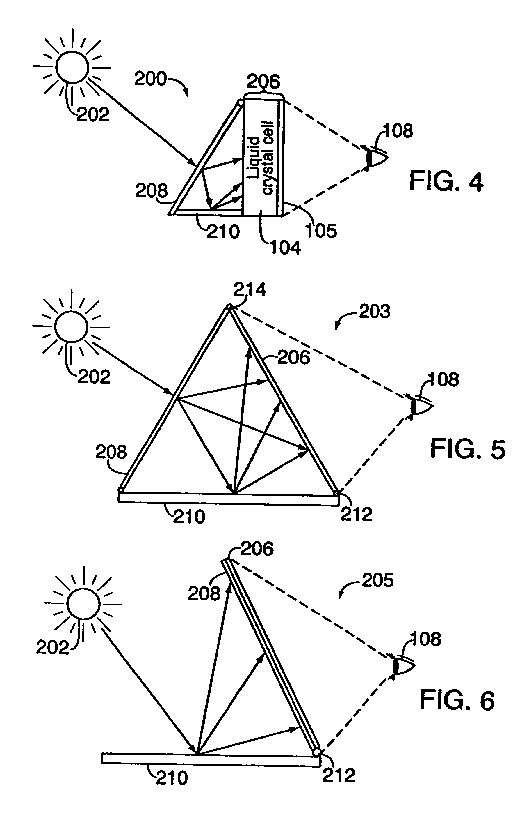
[0038]FIG. 4 illustrates a transmissive display device 200 implemented in accordance with one embodiment of the present invention. The display 200 comprises, e.g., a transmissive display panel 206 which comprises a protective outer layer, i.e., the screen 105, and an inner layer, implemented as a liquid crystal cell 104. A translucent diffuser 208 and diffuse reflector 210 are positioned behind the display panel 206 in an angular arrangement to form a back portion and a bottom portion, respectively, of the displ...


PUM


Abstract

Energy efficient transmissive and transreflective display devices use ambient light from a natural or artificial source to supplement light supplied by a backlight. Ambient light passes through a transmissive diffuser to a rear surface of a transmissive display panel. Additional energy efficiency is achieved by using one or more photo-sensors to detect the amount of ambient light and automatically adjusting the backlight intensity as a function of photo-sensor output. As a result, backlight intensity and power usage can be minimized while maintaining the viewability of images shown on the display.

Description


Claims


Application Information

Patent Timeline
Owner MICROSOFT TECH LICENSING LLC
Why Eureka
Try Eureka