Non-volatile magnetic memory device

a magnetic memory and non-volatile technology, applied in the field of magnetic memory devices, can solve the problems of complicating the fabrication process, prior art devices are typically not suitable for integration in a standard device integration process,

Inactive Publication Date: 2006-09-19
MICROMEM TECH
View PDF13 Cites 6 Cited by
  • Summary
  • Abstract
  • Description
  • Claims
  • Application Information

AI Technical Summary

Benefits of technology

[0010]In another aspect, separate magnetic elements are arranged about a sensing region of a sensor. The separate magnetic elements are magnetized by a common write line with separate magnetic fields. The magnetic fields create magnetic flux fields which pass thro...

Problems solved by technology

As a result, prior art devices are typically not suitable for integration in a standard device integration process due to the need for special highly sensitive m...

Method used


Image

  • Non-volatile magnetic memory device
  • Non-volatile magnetic memory device
  • Non-volatile magnetic memory device

Examples


second embodiment

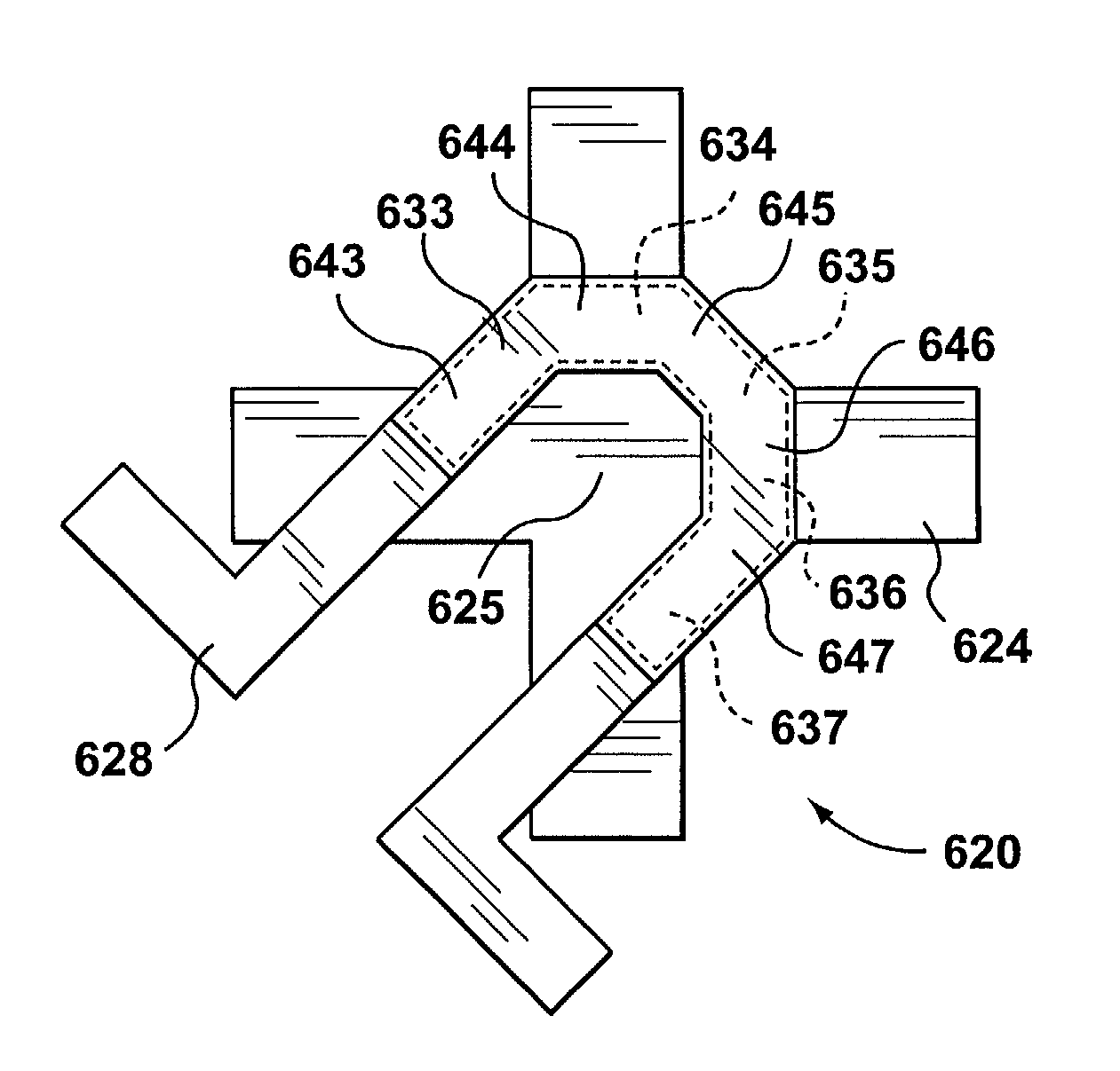
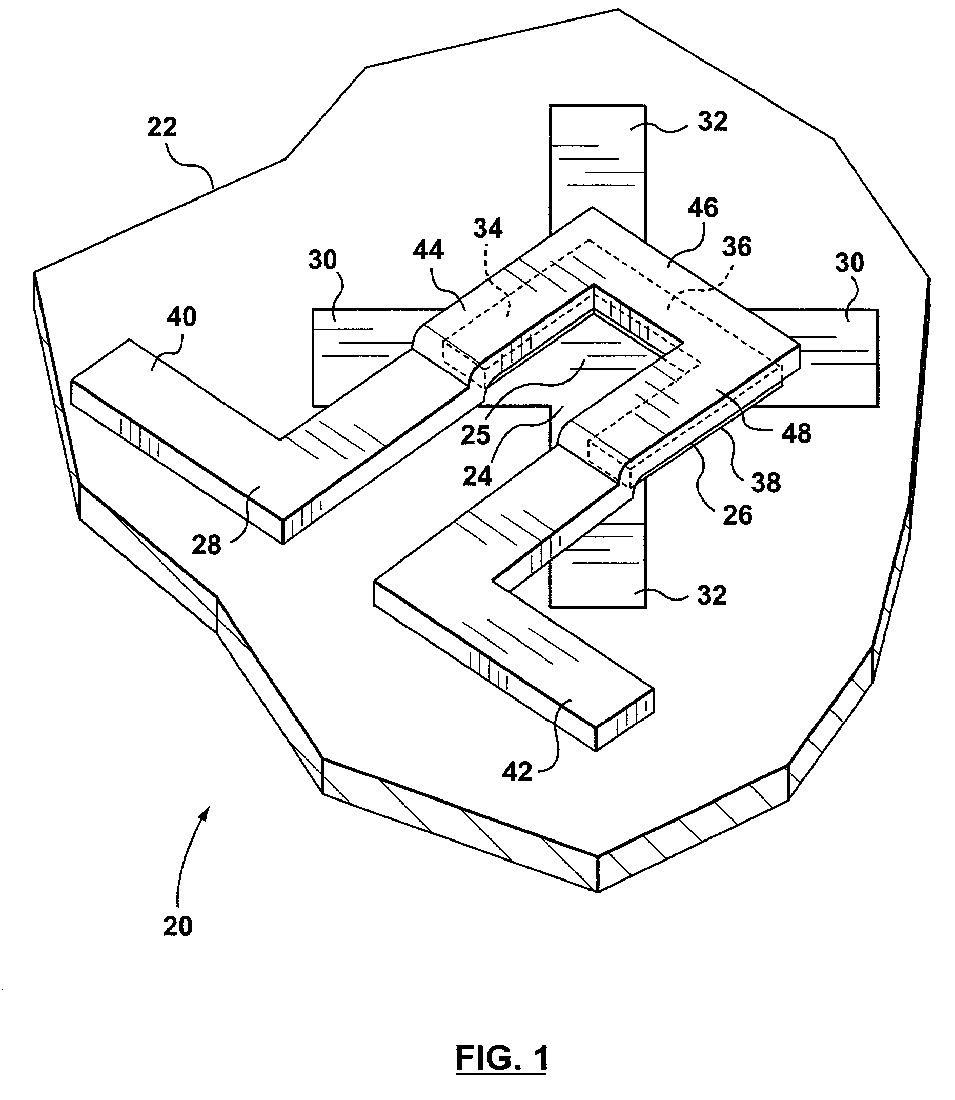
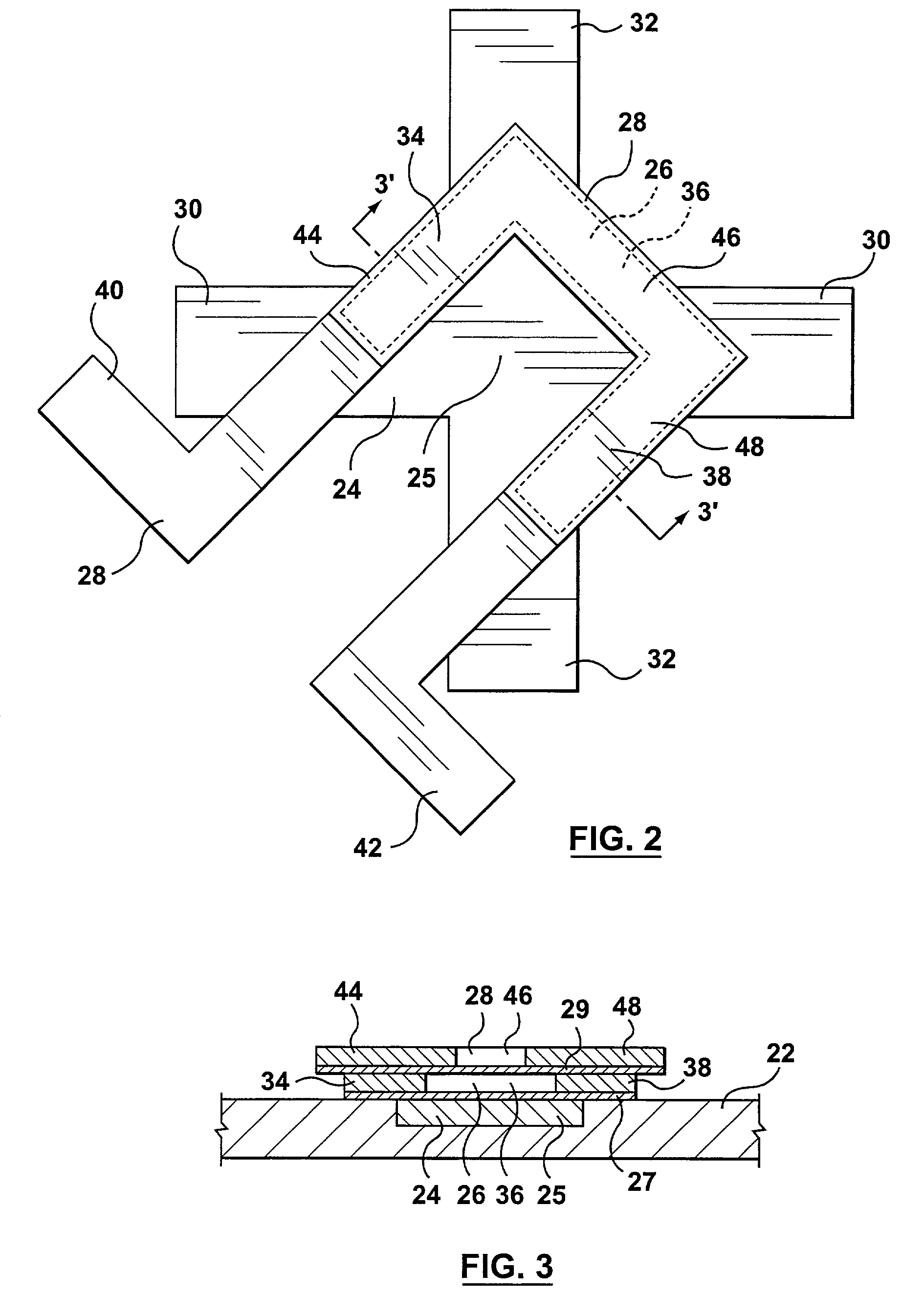
[0073]FIG. 11 illustrates a memory cell 220 according to the present invention. Memory cell 220 has a substrate (not shown), a sensor 224 formed in substrate, three separate magnetic elements 226a, 226b and 226c and a write line 228. Magnetic elements 226a, 226b and 226c are generally rectangular. One segment 244, 246 or 248 of write line 228 is aligned with each of the magnetic elements. The three magnetic elements 226a, 226b and 226c are responsive to write signals transmitted between terminals 240 and 242 of write line 228 to store remnant magnetic fields in their hard directions of magnetization 252, 256 and 260. Like segments 34, 36 and 38 of magnetic element 26 (FIG. 1), the magnetic fields may have their south poles towards the sensing region 225 of sensor 224 in a first orientation or may have their north poles towards sensing region 225 in a second orientation. The orientation of cell 220 may be sensed using sensor 224 in the same way as sensor 24 of cell 20 (FIG. 1).

third embodiment

[0074]FIG. 12 illustrates a memory cell 320 according to the present invention. Memory cell 320 is similar to memory cell 220 (FIG. 11), except that magnetic elements 326a, 326b and 326c are not rectangular. Instead, 326a, 326b and 326c approximate the shape of magnetic element 26, with a gap at corner regions 321a and 321b. Write line 328 and sensor 324 are used in the same way as write line 28 and sensor 24 to write data to cell 320 and to sense the data stored in cell 320.

fourth embodiment

[0075]FIG. 13 illustrates a memory cell 420 according to the present invention. Memory cell 420 has three separate rectangular magnetic elements 426a, 426b and 426c, which are arranged with their shorter dimension towards sensing region 425.


PUM


Abstract

A non-volatile magnetic memory cell having a magnetic element with multiple segments which are not co-linear. Each of the segments is magnetized with a remnant magnetic field using a single write line. The segments can be magnetized in a first direction or a second direction, corresponding to first and second orientations of the memory cell. A sensor is provided to determine the direction in which the segments are magnetized and thereby the orientation of the cell. The segments are oriented such that the magnetic flux fields created by their respective remnant magnetic fields have a cumulative effect at a sensing region of the sensor. The cumulative effect allows a less sensitive sensor to be used than in known device. In various embodiments, the magnetic element can have a number of linear segments or a curved profile. In another embodiment, multiple magnetic elements are magnetized by a single write line. The multiple magnetic elements are arranged such that remnant magnetic field stored in them can be cumulatively sensed. In another embodiment, the magnetic element is arranged to be magnetized in a single general direction, but is shaped such that magnetic flux lines emanate from it in different directions. The different directions are arranged to direct flux lines through the sensing region of a sensor, which measures their cumulative effect.

Description

[0001]This application claims the benefit of Provisional Application No. 60 / 242,396, filed Oct. 20, 2000.FIELD OF THE INVENTION[0002]This invention relates to magnetic memory devices. More particularly, it relates to a non-volatile magnetic memory cell.BACKGROUND OF THE INVENTION[0003]Non-volatile magnetic memory cells have been known for some time. Prior art devices have utilized a geometrically simple linear magnetic element to store a magnetic field. The magnetic field can typically have one of two orientations, which are arbitrarily assigned to represent “0” and “1” bit values. The prior art devices typically utilize a Hall effect sensor to detect the orientation of the magnetic field, thereby determining the data value stored in the cell.[0004]The geometrically simple linear magnetic elements typically require a more sensitive sensor to determine the orientation of their stored magnetic fields. As a result, prior art devices are typically not suitable for integration in a stand...

Claims


Application Information

Patent Timeline
IPC IPC(8): G11C7/02G11C11/15
CPCG11C11/15G11C11/1675
Inventor STEPHENSON, JAMESSHIPLEY, BRUCECAROTHERS, DAN
Owner MICROMEM TECH
Why Eureka
Try Eureka