Wireless LAN with dynamic channel selection

a dynamic channel and wireless lan technology, applied in the field of communication systems, can solve the problems of unlicensed spectrum, time-consuming and laborious, and waiting for probe requests can take up to 50 ms

Active Publication Date: 2006-09-19
ALCATEL-LUCENT USA INC
View PDF12 Cites 47 Cited by
  • Summary
  • Abstract
  • Description
  • Claims
  • Application Information

AI Technical Summary

Benefits of technology

[0041]The present invention is based on passive listening and does not depend on correspondence from other APs, made by other manufacturers. So, it is better suited for the unlicensed band than systems known from the prior art. Moreover, an access point in the present invention, because of direct measurement, is evaluating the interference in a much more precise way than in the prior art where the interference was estimated. Furthermore, an access point in the present invention is able of determining the load of other APs without the need for sending load information by way of Probe Responses and Probe Requests. The present invention is based on altering the duration of passive listening, so an AP can adjust the total scanning period depending on the load. Besides this, access points in the present invention can, by listening on their operating channel and recording the interference on it, decide when to change channels.

Problems solved by technology

So it is very likely that this load information will never be obtained from APs made by other manufacturers.
Therefore it does not solve the problem of unlicensed spectrum.
Secondly, waiting for the Probe Requests can take up to 50 ms if the other AP is very busy.
This situation is highly undesirable especially if the AP sending the Probe Request is highly loaded.
Thirdly, the strategy as described in [Kamerman, 1999] lacks a strategy about when to change channels.
This is a very long time and a lot of changes in circumstances can take place.
A microwave oven could come on and go off within that time, causing a decrease in throughput of an AP.
The problem lies in the fixed scan interval and the fact that all channels are scanned one after the other.

Method used


Image

  • Wireless LAN with dynamic channel selection
  • Wireless LAN with dynamic channel selection
  • Wireless LAN with dynamic channel selection

Examples


Embodiment Construction

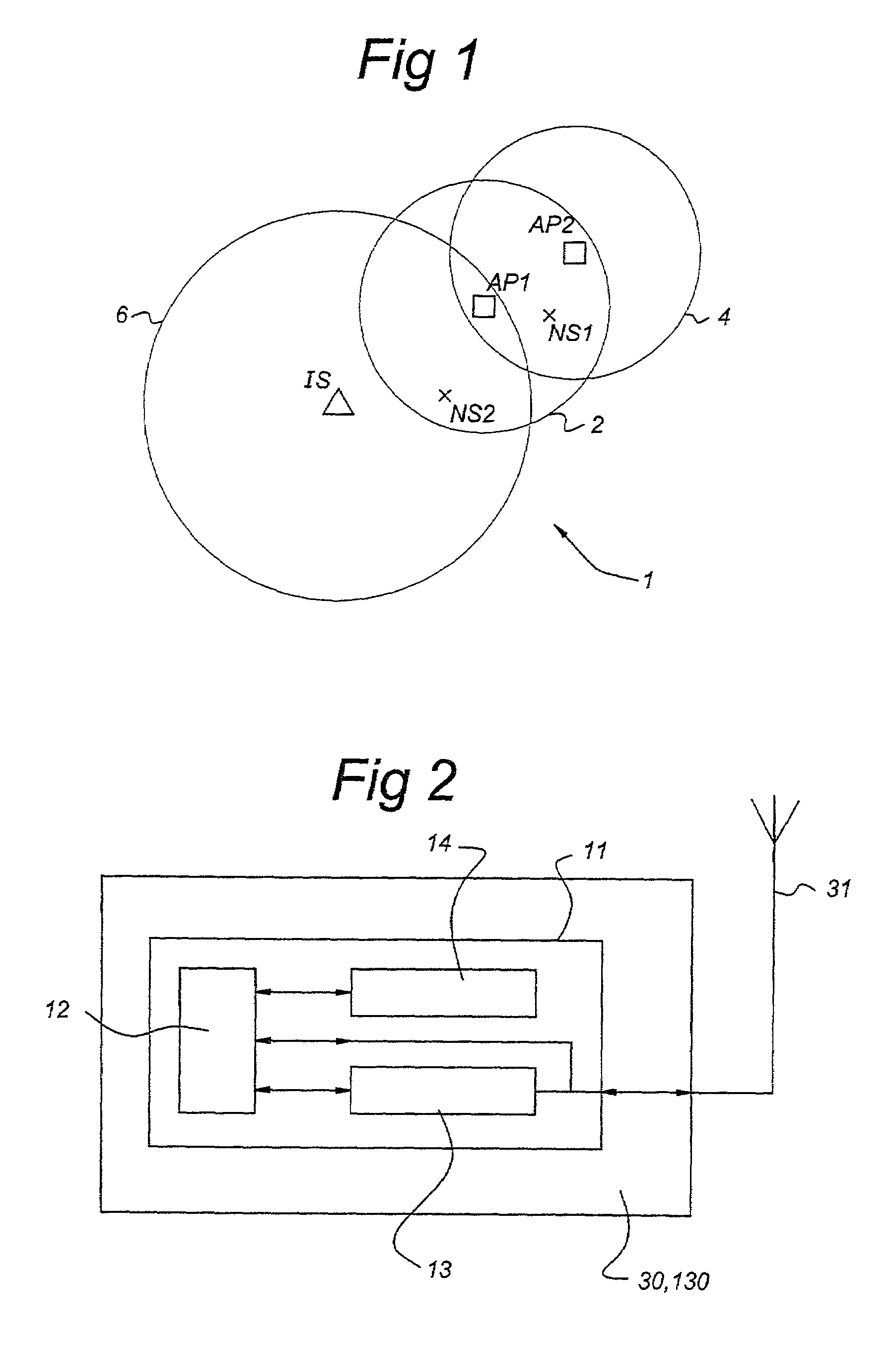
[0049]In FIG. 1, a wireless LAN 1 and two of its access points AP1, AP2 with cells 2, 4 are shown. Also two network stations NS1, NS2 are shown. Access point AP1 is serving cell 2 and access point AP2 has its own cell 4. The boundaries of cell 2 are defined by the carrier detect threshold (CT) used by the network stations NS1, NS2 and the access point AP1. Outside the cell 2, the receive level of signals coming from AP1 will be lower than the CT, so network stations located outside cell 2 will not be able to communicate (be associated) with AP1. The area outside cell 2 is covered by other APs within the same wireless LAN or is not part of the wireless LAN at all. Both network stations NS1 and NS2 are operating on an operating channel C1 of access point AP1.

[0050]In FIG. 1, an interfering source IS is located in such a way that it will cause interference at the location of AP1. The source IS is transmitting on the same frequencies as AP1. The circle 6 depicts the positions in which t...


PUM


Abstract

The present invention describes an algorithm for the assignment of channels used by access points (APs) in wireless LANs in a dynamic way in order to achieve the best performance. The assignment of channels is based on a procedure in which an AP is passively listening on the other channels during idle time. The AP is calculating the optimal channel with the least interference and sharing. If the AP experiences too much disturbance, it will decide to switch to the calculated optimal channel.

Description

CROSS REFERENCE TO RELATED APPLICATION[0001]This application claims priority of European Application No. 01304113.2 filed on May 8, 2001.FIELD OF THE INVENTION[0002]The present invention relates to a communication system comprising a plurality of access points (APs) and network stations, each said network station being arranged to communicate with one of said access points through a wireless communication protocol.BACKGROUND OF THE INVENTION[0003]Wireless local area networks (LANs) have been developed as an enhanced replacement for wired LANs. In a wireless LAN for data-communication a plurality of (mobile) network stations (e.g., personal computers, telecommunication devices, etc.) are present that are capable of wireless communication. As compared to wired LANs, data-communication in a wireless LAN can be more versatile, due to the flexibility of the arrangement of network stations in the area covered by the LAN, and due to the absence of cabling connections.[0004]Wireless LANs ar...

Claims


Application Information

Patent Timeline
Patent Type & Authority Patents(United States)
IPC IPC(8): H04Q7/00H04L12/28H04W24/00H04W28/04H04W72/04H04W84/12H04W88/08
CPCH04W72/02H04W24/00H04W28/04H04W88/08H04W84/12
Inventor MALHOTRA, RICHABUSCH, PATRICK
Owner ALCATEL-LUCENT USA INC
Why Eureka
Try Eureka