Device for controlling drives in machine tools or production machines

a technology for controlling drives and production machines, applied in the direction of program control, instruments, nuclear elements, etc., can solve the problems of inability to evaluate if, inability to further process directly by a supervisory automation plane or internet service, and inability to precisely synchronize application programs and trace modules, etc., to achieve excellent testing functionality and easy and clear evaluation of test results

Inactive Publication Date: 2006-09-19
SIEMENS AG
View PDF4 Cites 7 Cited by
  • Summary
  • Abstract
  • Description
  • Claims
  • Application Information

AI Technical Summary

Benefits of technology

[0011]According to an advantageous embodiment of the invention, the device can further include a device controller that controls the device, wherein a time when the trace module is triggered or parameters present in the device controller at the time when the trace module is triggered can be stored in the storage medium. In this way, the trigger time and the parameter configuration at the trigger time are also reliably stored for each file, so that the test conditions and test runs can be readily reproduced for any later point in time. In particular, such additional files are very important for a subsequent error diagnosis if the trace module is triggered after an error has been detected.
[0028]According to yet another advantageous embodiment, the storage medium can also store parameter sets for configuring the trace module or the function generator. In this way, the user can define for the controller of the device different predefined excitation signals by selecting different parameter sets and record different actual process values.

Problems solved by technology

However, the application program and the trace module are not precisely synchronized.
These deviations are displayed on the user interface of the controller, but cannot be further processed directly by a supervisory automation plane or Internet services.
The user can therefore not evaluate if, for example, the variation in the actual rotation speed during a change of the desired rotation speed stays within an acceptable limit, because for example process reference values recorded during the startup of the machine are no longer available for comparison.
Another problem is that for a comprehensive evaluation, a startup / diagnostic device must always be connected to the device that controls the drive(s).

Method used


Image

  • Device for controlling drives in machine tools or production machines
  • Device for controlling drives in machine tools or production machines
  • Device for controlling drives in machine tools or production machines

Examples


Embodiment Construction

[0033]Throughout all the Figures, same or corresponding elements are generally indicated by same reference numerals. These depicted embodiments are to be understood as illustrative of the invention and not as limiting in any way. It should also be understood that the drawings are not necessarily to scale and that the embodiments are sometimes illustrated by graphic symbols, phantom lines, diagrammatic representations and fragmentary views. In certain instances, details which are not necessary for an understanding of the present invention or which render other details difficult to perceive may have been omitted.

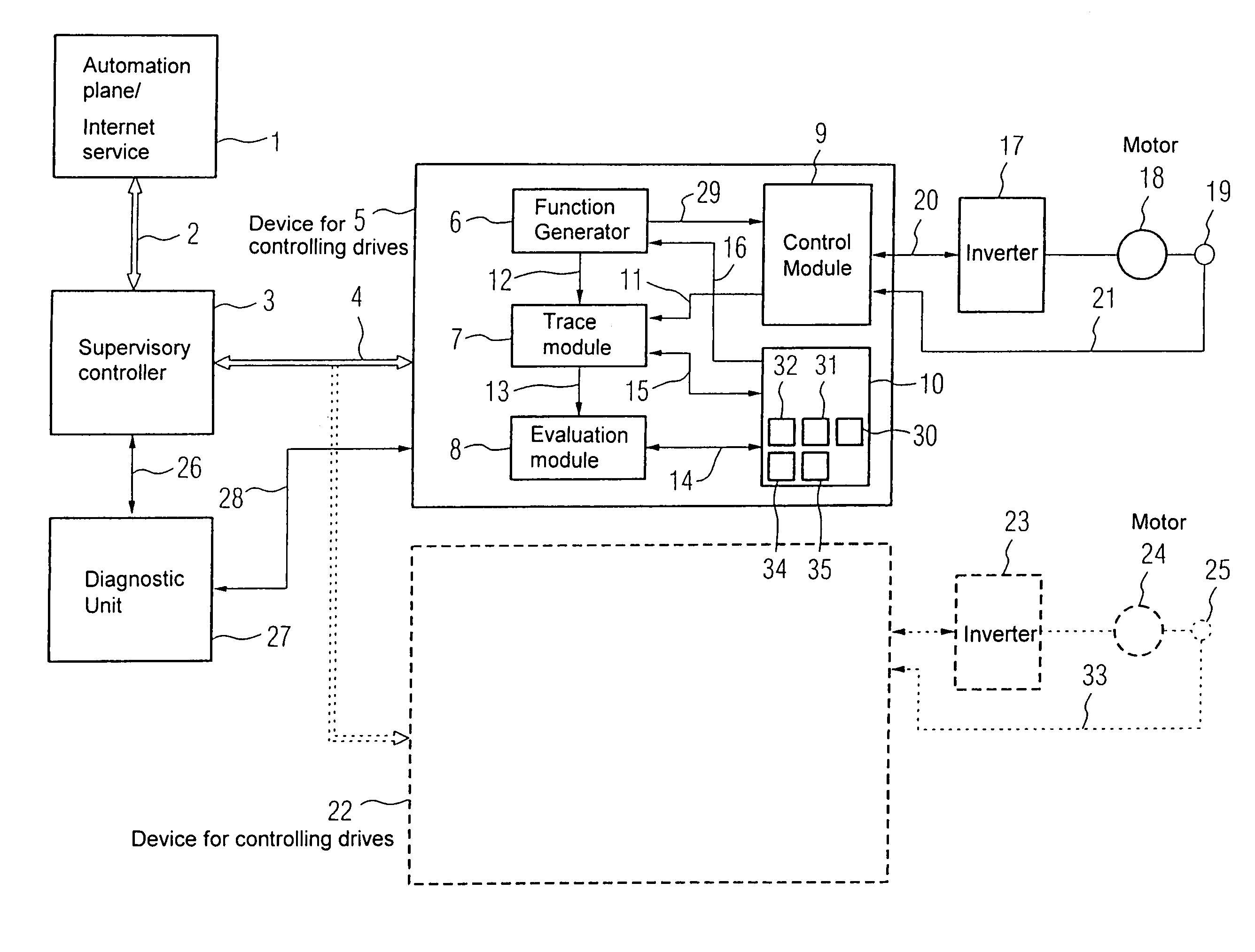
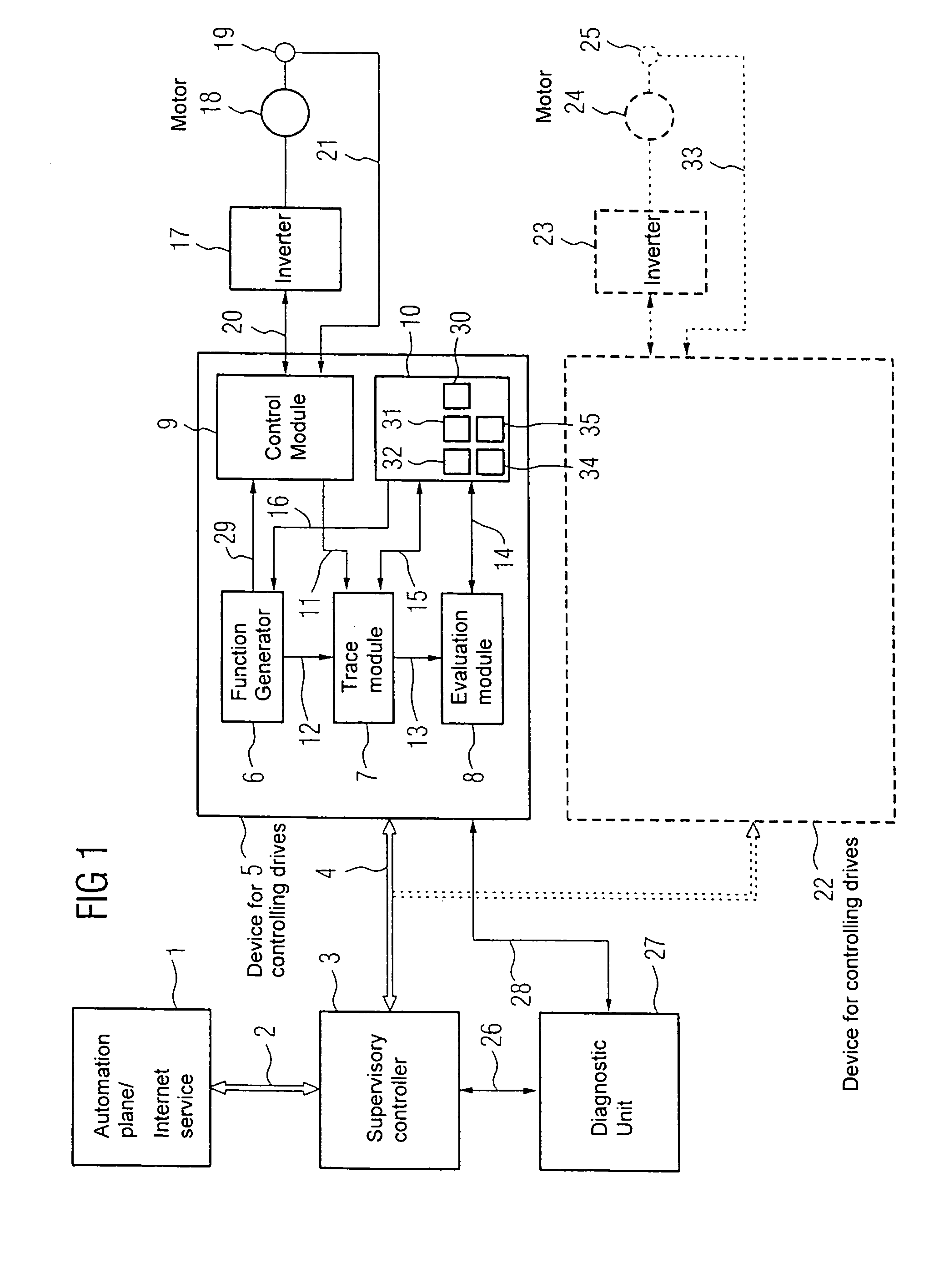
[0034]Turning now to the drawing, and in particular to FIG. 1, there is shown in the form of a schematic block diagram an exemplary device 5 according to the invention for controlling drives, as well as optionally connected peripheral devices. The illustrated embodiment of the device 5 according to the invention includes a function generator 6, a trace module 7, an evaluation ...


PUM


Abstract

A device for controlling drives of machine tools or production machines is disclosed, whereby the device includes a permanent storage medium associated with the device and a trace module that records actual process values after the trace module is triggered. The actual process values are permanently stored on the permanent storage media in form of files in a standard file format. The device makes it possible to permanently store actual process values recorded by a trace functionality, in particular by a trace module, in the device for controlling drives in a standard data format.

Description

CROSS-REFERENCES TO RELATED APPLICATIONS[0001]This application claims the priority of German Patent Application, Serial No. 103 39 731.0, filed Aug. 28, 2003, pursuant to 35 U.S.C. 119(a)–(d), the disclosure of which is incorporated herein by reference.BACKGROUND OF THE INVENTION[0002]The present invention relates, in general, to a device for controlling drives in machine tools or production machines.[0003]Nothing in the following discussion of the state of the art is to be construed as an admission of prior art.[0004]In a modern machine tool or production machine, which can include, for example, a motor with a connected gear and load, a controller is typically associated with each drive. One controller can hereby simultaneously control several motors. The efficiency and the quality of almost all drives in machine tools and production machines depend directly on an optimized dynamic characteristic of the drive controller. A suitable test functionality for ensuring the desired contro...

Claims


Application Information

Patent Timeline
Patent Type & Authority Patents(United States)
IPC IPC(8): G06F19/00G06F15/00G05B19/408
CPCG05B19/408G05B19/406
Inventor BECKER, ARNDHEIDL, THOMASHEINEMANN, GERHARD
Owner SIEMENS AG
Why Eureka
Try Eureka