
Finite impulse response (FIR) filter compiler

Inactive Publication Date: 2006-09-19
ALTERA CORP
View PDF5 Cites 16 Cited by
  • Summary
  • Abstract
  • Description
  • Claims
  • Application Information

AI Technical Summary

Benefits of technology

[0015]In yet another embodiment, a method of building a decimating FIR filter by a compiler using a plurality of domain polyphases wherein each of the plurality of polyphases is represented by a serial filter and wherein a single clock domain is used for each serial filter is disclosed. A first clock rule is applied when an input data width is less than or equal to a decimation factor and a second clock rule is applied when an input data width is greater than the decimation factor.
[0016]In a preferred embodiment, the first clock rule includes the following operations, a clock rate is set to an input data rate and an output data rate is set equal to the input data divided by the decimation factor. The input data is held for a quantity N clock cycles where the quantity N is equal to the decimation factor such that all polyphases are switched through at every clock cycle. Whereas the second clock rule includes the following operations, the clock rate is set equal to a speed multiplication factor (SMF1) multiplied by the input data rate where the SMF is a smallest integer such that the SMF1 multiplied by the decimation factor is greater than or equal to the input data width. The output data rate is set equal to the SMF multiplied by the input data rate divided by the decimation factor and the output data rate is held for a quantity L clock cycles, wherein the quantity L is equal to the SMF1 multiplied by the decimation factor, such that all polyphases are switched through at every quantity SMF1 clock cycles.
[0017]In still anot

Problems solved by technology

Unfortunately, however, since FIR filters are of a higher order than are IIR filters, implementing a FIR filter is generally more computationally expensive.
Unfortunately however, conventional approaches to implementing a particular FIR filter in a PLD is time consuming and expensive.
This long cycle time increases costs, slows introduction of new products, and delays release of system upgrades all of which negatively affect profitability and new product introductions.

Method used


Image

  • Finite impulse response (FIR) filter compiler
  • Finite impulse response (FIR) filter compiler
  • Finite impulse response (FIR) filter compiler

Examples


Embodiment Construction

[0035]The following description is provided to enable any person skilled in the art to make and use the invention and sets forth the best modes contemplated by the inventor for carrying out the invention. Various modifications, however, will remain readily apparent to those skilled in the art, since the basic principles of the present invention have been defined herein specifically to provide a novel FIR filter compiler and methods of use thereof.

[0036]Reference will now be made in detail to an embodiment of the invention. An example of the embodiment is illustrated in the accompanying drawings. While the invention will be described in conjunction with an embodiment, it will be understood that it is not intended to limit the invention to one preferred embodiment. To the contrary, it is intended to cover alternatives, modifications, and equivalents as may be included within the spirit and scope of the invention as defined by the appended claims.

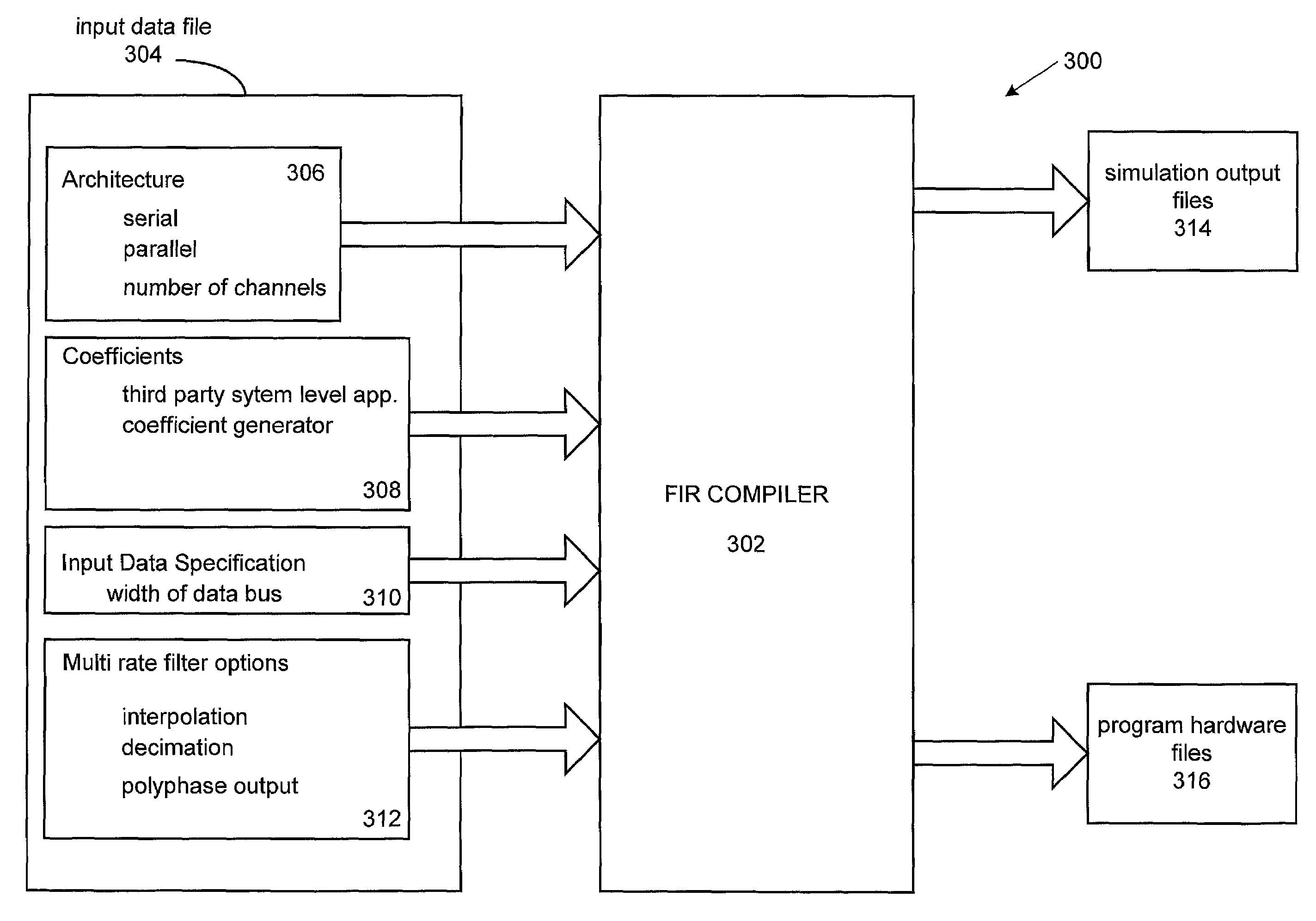
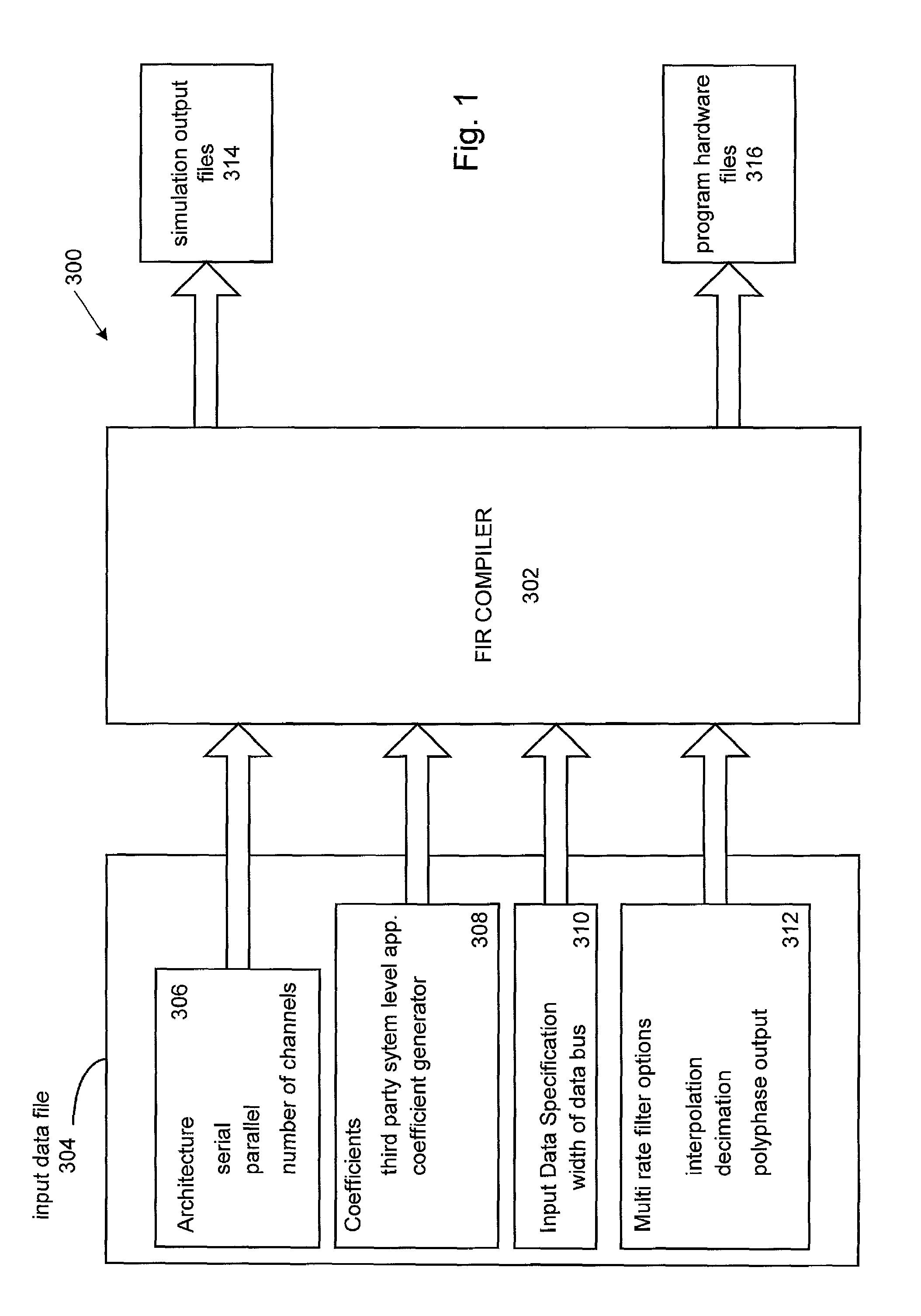
[0037]Broadly speaking, an apparatus, s...


PUM


Abstract

A method, apparatus and system for building a filter is disclosed. In a particular embodiment, the filter is a finite impulse response (FIR) filter and a compiler suitable for implementing the FIR filter is described. The compiler has a filter coefficient generator suitably arranged to provide a first set of filter coefficients corresponding to the desired FIR filter spectral response and a filter spectral response analyzer coupled to the filter coefficient generator for providing expected FIR filter spectral response based in part upon the first set of filter coefficients. The compiler also includes a filter resource estimator coupled to the filter spectral response simulator for estimating an implementation cost of the FIR filter based upon the second set of filter coefficients as well as a filter compiler unit coupled to the resource estimator arranged to compile a FIR filter implementation output file.

Description

CROSS REFERENCE TO RELATED APPLICATIONS[0001]This application claims benefit of priority under 35 U.S.C. 119(e) of (i) U.S. Provisional Application No. 60 / 184,226 filed Feb. 23, 2000 and entitled “FINITE IMPULSE RESPONSE (FIR) FILTER COMPILER”, (ii) U.S. Provisional Application No. 60 / 184,736, filed Feb. 23, 2000 and entitled “FINITE IMPULSE RESPONSE (FIR) FILTER COMPILER FOR PROVIDING A SINGLE CLOCK DOMAIN FOR A DECIMATING FIR WITH POLYPHASE DECOMPOSITION AND SERIAL ARITHMETIC”, (iii) U.S. Provisional Application No. 60 / 184,396, filed Feb. 23, 2000 and entitled “FINITE IMPULSE RESPONE (FIR) FILTER COMPILER FOR PROVIDING A SINGLE CLOCK DOMAIN FOR AN INTERPOLATING FIR FILTER WITH POLYPHASE DECOMPOSITION AND SERIAL ARITHMETIC, and (iv) U.S. Provisional Application No. 60 / 186,575 filed Mar. 2, 2000 and entitled “FINITE IMPULSE RESPONSE (FIR) FILTER COMPILER”, each of which are incorporated by reference in their entireties.BACKGROUND OF THE INVENTION[0002]1. Field of Invention[0003]This...

Claims


Application Information

Patent Timeline
IPC IPC(8): G06F17/50G06F7/60
CPCG06F17/5054G06F30/34
Inventor SAN, TONYMOLSON, PHILIPPE
Owner ALTERA CORP
Features
  • Generate Ideas
  • Intellectual Property
  • Life Sciences
  • Materials
  • Tech Scout
  • Unparalleled Data Quality
  • Higher Quality Content
  • 60% Fewer Hallucinations
Learn More