Ratchetable open-ended wrench

a technology of open-ended wrenches and wrenches, which is applied in the field of open-ended wrenches, can solve the problems of structural failures which can occur in the second jaw of wrenches, and achieve the effect of reducing the torque-related stress within the material and increasing the use of tools

Inactive Publication Date: 2006-09-26
DIMON HUGBUNADARHUS EHF
View PDF18 Cites 56 Cited by
  • Summary
  • Abstract
  • Description
  • Claims
  • Application Information

AI Technical Summary

Benefits of technology

[0009]Another object of this invention is to provide an improved ratchetable open-ended wrench that is able to withstand the rough abuse to which open-ended wrenches are subjected under normal use and abuse.
[0026]The ratchetable open-ended wrenches of this invention provide important advantages over prior ratchetable open-ended wrenches, making the invention highly desirable for use in a wide variety of applications and increasing usage of tools of this type.

Problems solved by technology

These figures illustrate major structural failures which can occur in the second jaw of wrenches of the prior art if the wrenches are used for purposes for which they are not intended or if “too much” torque is applied.

Method used


Image

  • Ratchetable open-ended wrench
  • Ratchetable open-ended wrench
  • Ratchetable open-ended wrench

Examples


Embodiment Construction

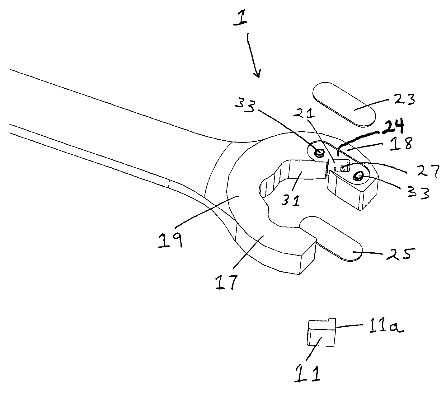
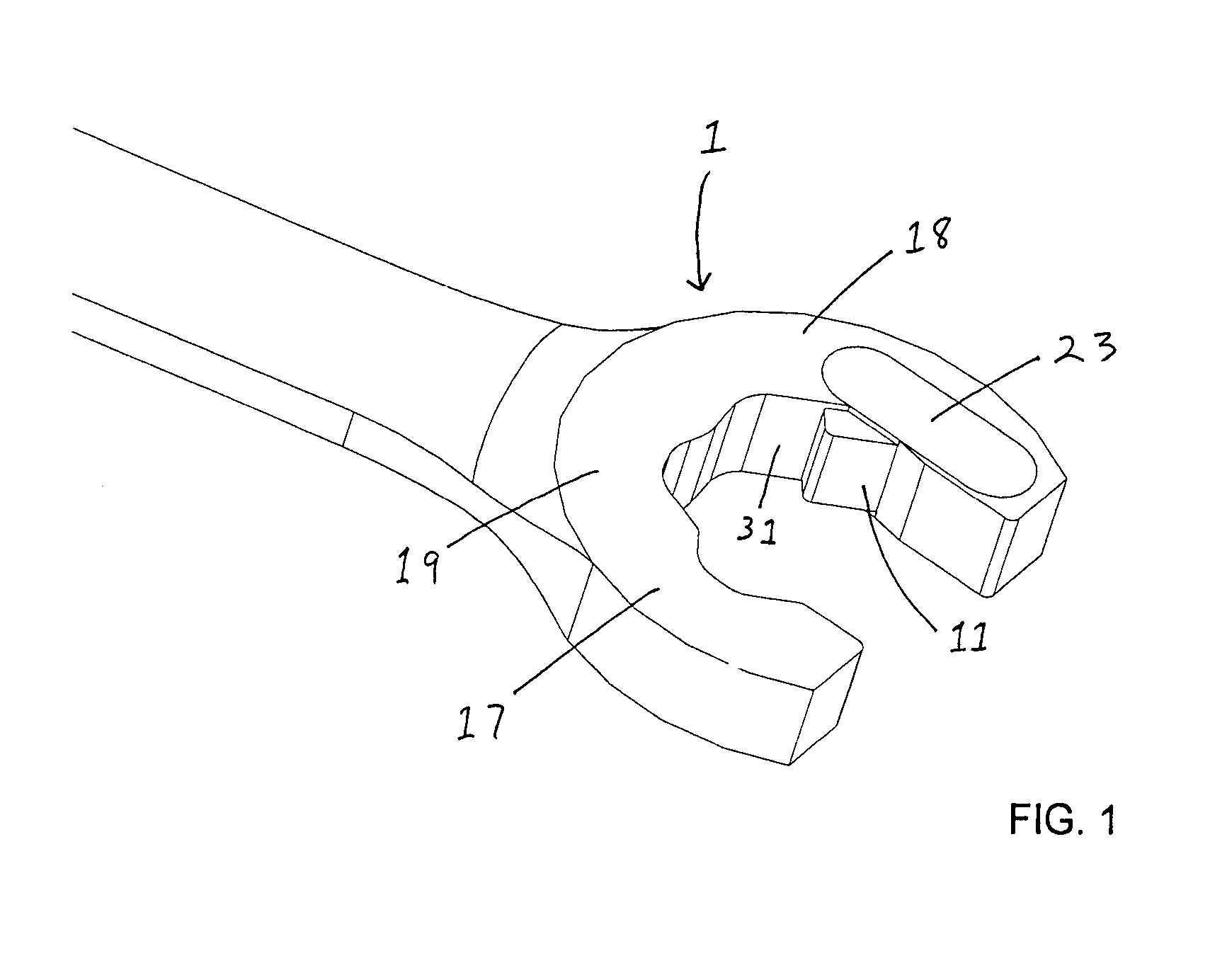
[0038]FIG. 1 is a full perspective view of the jaw end of one embodiment of the improved ratchetable open-ended wrench 1. Wrench 1 in this embodiment has a first jaw 17 and a second jaw 18 connected by a base area 19. Wrench 1 further includes a retractable jaw member 11 that is slidable within a slot 21 (not shown in FIG. 1) along an axis of motion parallel to a support surface 31 of second jaw 18. Retractable jaw member 11 in FIG. 1 is shown in a fully-extended position with retractable jaw member 11 in its position closest to base area 19. A cover plate 23 is recessed into second jaw 18, thereby limiting the lateral movement of retractable jaw member 11 within slot 21 (not shown in FIG. 1). Cover plate 23 is welded to second jaw 18 in order to form a load-bearing structural member within second jaw 18. In certain preferred embodiments of the invention, a cover plate 25 (not shown in FIG. 1) is recessed into the opposing face of second jaw 18, serving the same functions as cover p...


PUM


Abstract

A ratchetable open-ended wrench having a slidable retractable jaw member in a slot in one of its jaws and having a cover plate, preferably two cover plates, welded to the jaw in a manner such that the cover plate forms a load-bearing structural member within the jaw.

Description

FIELD OF THE INVENTION[0001]This invention is related to open-ended wrenches and, in particular, to ratchetable open-ended wrenches.BACKGROUND OF THE INVENTION[0002]Open-ended wrenches have numerous applications wherever any of various rotatable elements such as hexagonal nuts or bolts need to be tightened or loosened. The open-ended variety of wrench is especially useful where tight spaces restrict the use of socket wrenches or other closed-end tools. The difficulty with these wrenches, however, is that when the user is using it to turn an element in anything but the most unrestricted of spaces, the wrench must be removed from the rotatable element and repositioned every fraction of a turn due to interference with other obstructions. Thus, without adequate space for a full 360-degree turn of the handle, multiple turning strokes must be applied, with repositioning necessary after each stroke. This shortcoming slows the rate at which the rotatable element is driven or loosened, makin...

Claims


Application Information

Patent Timeline
Patent Type & Authority Patents(United States)
IPC IPC(8): B25B13/12B25B13/08B25B13/46
CPCB25B13/46B25B13/08B25B13/00
Inventor PRADELSKI, WILLIAM W.
Owner DIMON HUGBUNADARHUS EHF
Why Eureka
Try Eureka