Self-attaching nut

a self-attaching and nut technology, applied in the direction of threaded fasteners, screwed fasteners, manufacturing tools, etc., can solve the problems of unthreaded bores, achieve optimum torque resistance, improve the push-off strength of fasteners and panel assemblies, and improve the retention of self-attaching nuts

Inactive Publication Date: 2006-09-26
PENN AUTOMOTIVE INC
View PDF44 Cites 47 Cited by
  • Summary
  • Abstract
  • Description
  • Claims
  • Application Information

AI Technical Summary

Benefits of technology

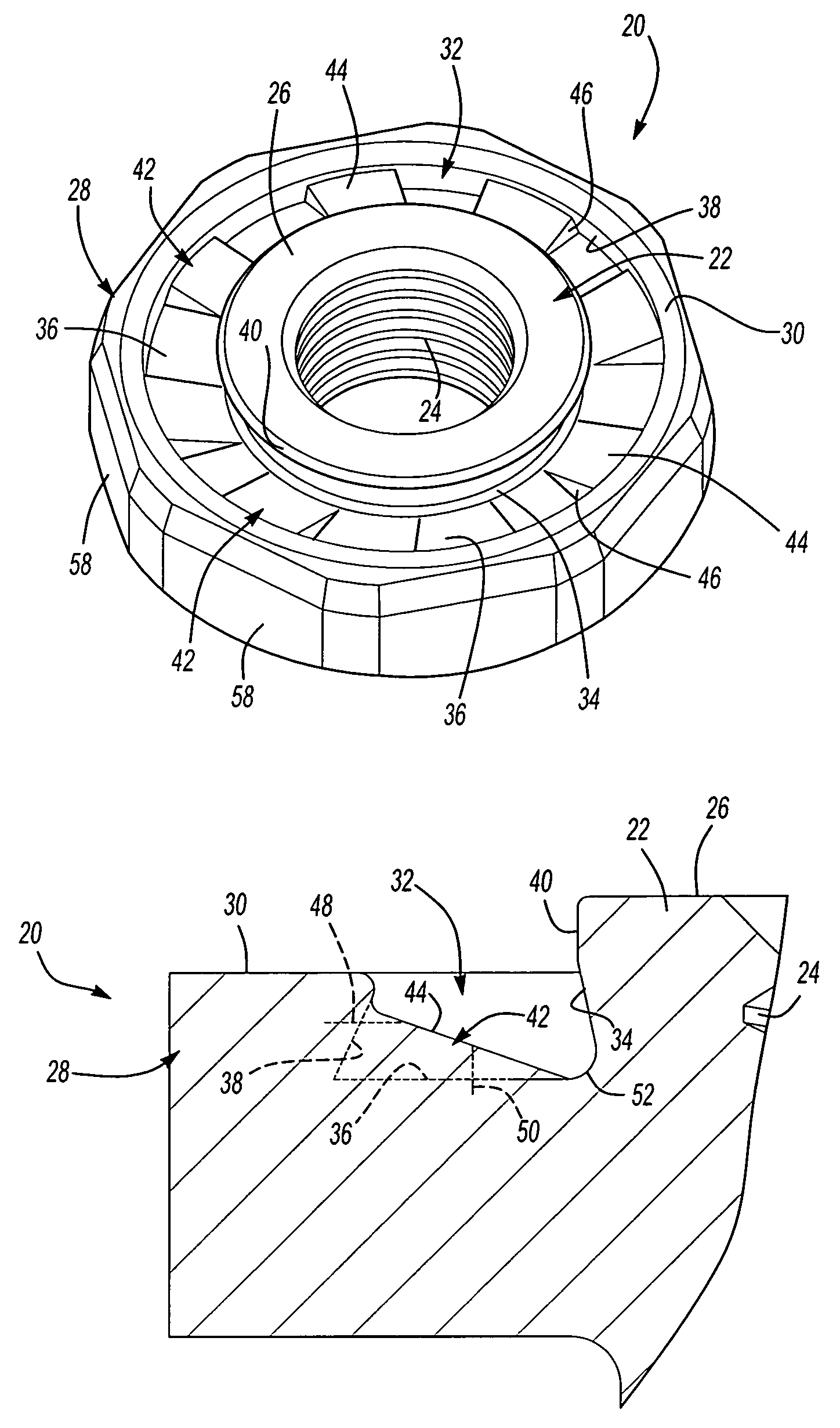
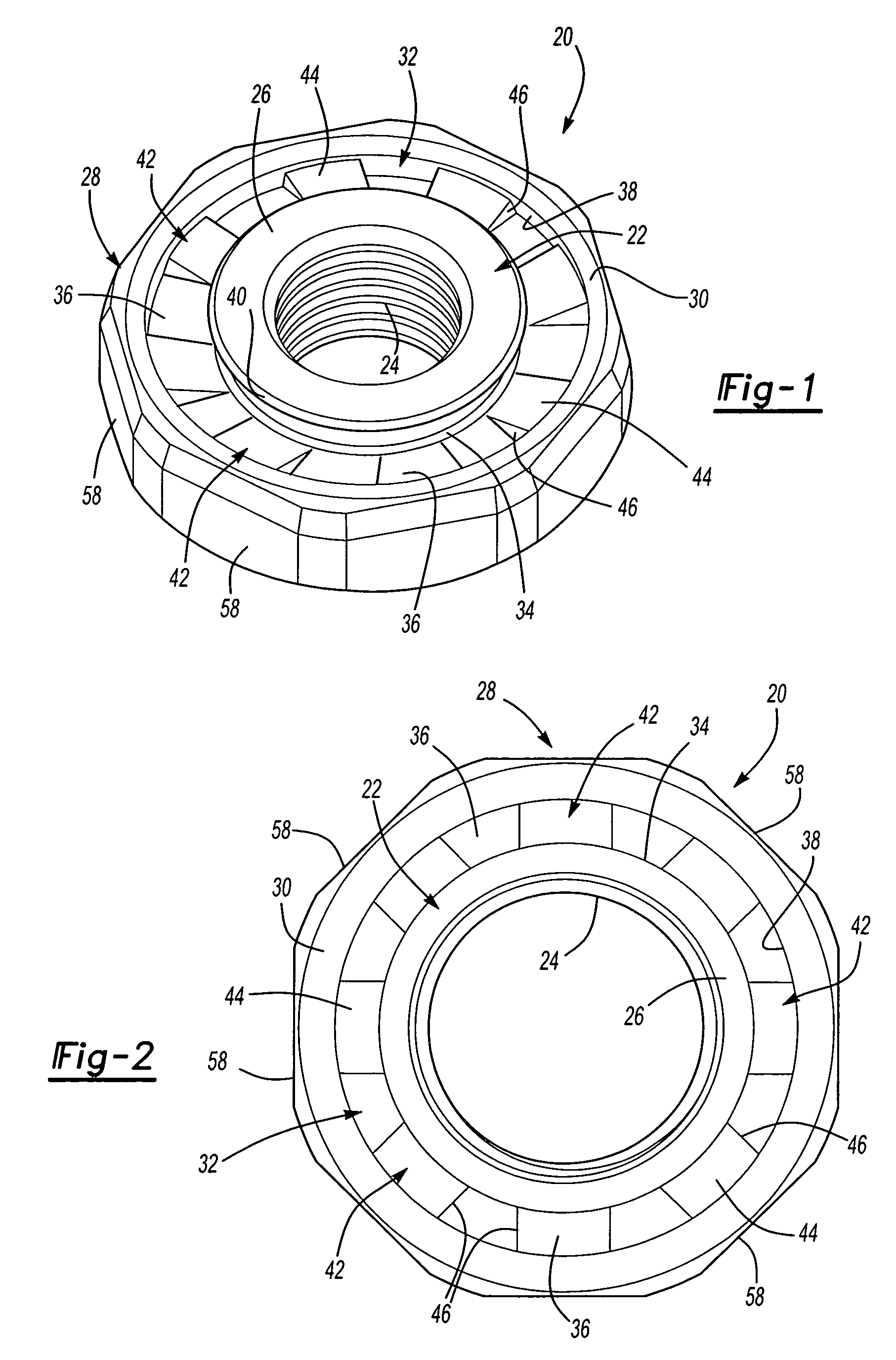
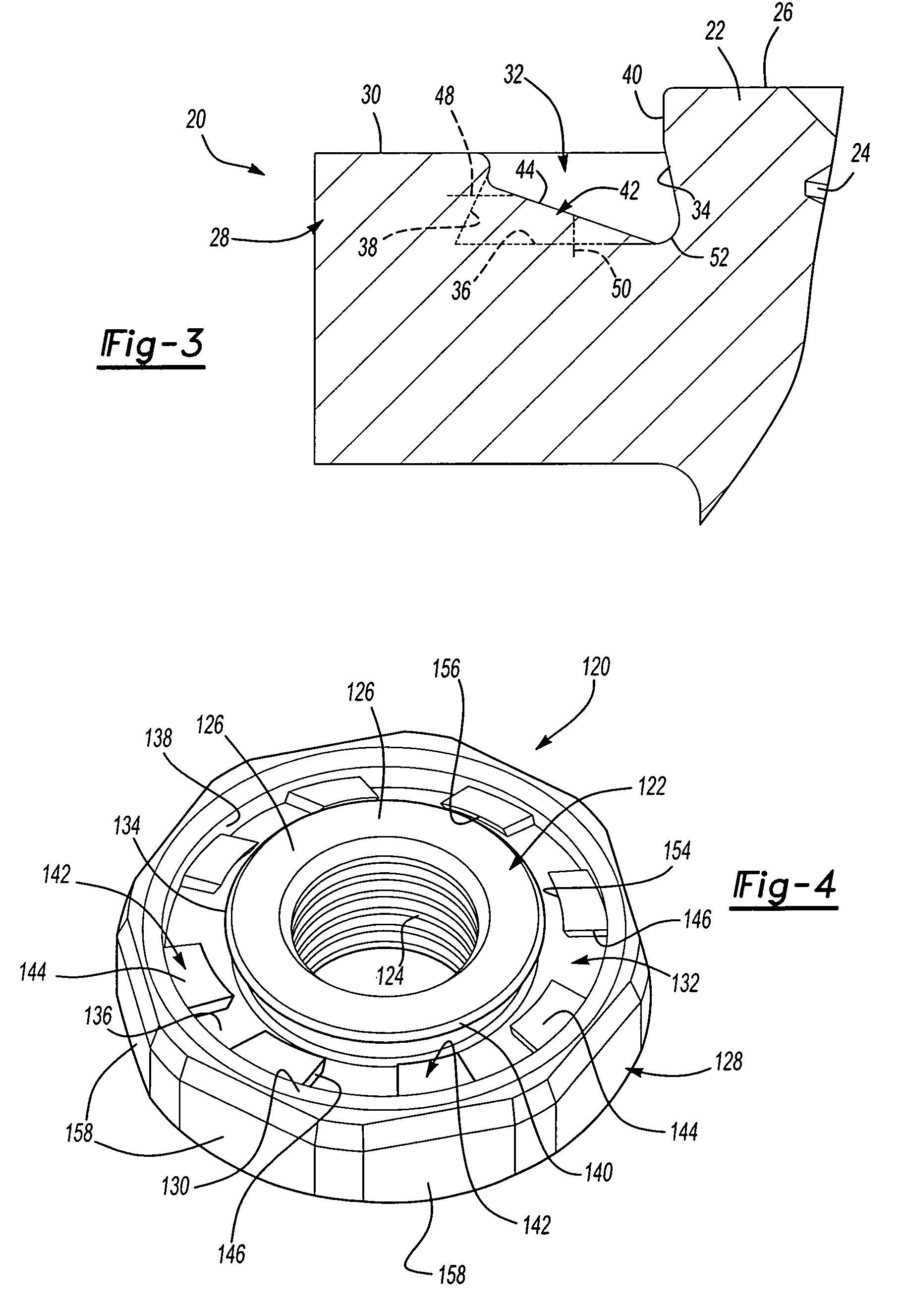
[0007]In the preferred embodiment of the self-attaching nut of this invention, at least one of the inner and outer side walls of the annular groove is inclined toward the other side wall forming a restricted opening to the annular groove adjacent the annular end face of the flange portion surrounding the annular groove. In the preferred embodiment, the outer side wall of the annular groove is inclined toward the pilot portion, providing improved retention of the self-attaching nut on a panel. In a most preferred embodiment, the outer side wall of the annular groove is inclined toward the pilot portion and the inner side wall is inclined from the bottom wall of the annular groove toward the outer side wall forming, a “dovetail-shaped” annular groove providing further improved retention of the self-attaching nut on a panel, which is generally referred to as the “push-off” strength of the fastener. The push-off strength of the fastener is critical in many applications because a male threaded fastener is received through the panel into the bore of the fastener and threaded into the bore typically with a torque wrench in mass production applications. The flange portion includes an annular end surface surrounding the pilot portion, which prevents the fastener from being pushed through the panel. In a typical application, the bore will be prethreaded. However, the bore may also be unthreaded for receipt of a thread forming or thread rolling male fastener, such as a bolt.
[0008]The self-attaching nut of this invention includes a plurality of circumferentially spaced radial ribs integral with the bottom wall and preferably the outer side wall of the annular groove, wherein the outer side wall is inclined toward the pilot portion and the radial ribs extend beyond a midportion of the bottom wall of the annular groove, but spaced from the inner side wall. Each of the radial ribs includes a top face spaced above the bottom wall of the annular groove and opposed preferably planar side faces which prevent rotation of the self-attaching nut relative to a panel deformed into the annular groove against the bottom wall as described above. In one preferred embodiment of the self-attaching nut of this invention, the top face of the radial ribs are rectangular and inclined from the outer side wall of the annular groove toward the bottom wall and the top face extends to adjacent the inner side wall of the annular groove. In this embodiment, the bottom wall of the groove extends generally perpendicular to the axis of the bore through the pilot portion and the top faces of the radial ribs extend to or adjacent the junction of the inner wall and the bottom wall of the annular groove, providing optimum torque resistance. It should also be noted that this embodiment reduces the likelihood of distortion of the thread cylinder of the bore through the central pilot portion, but assures substantially complete filling of the undercut formed by the inclined inner side wall of the annular groove, particularly when compared to self-attaching nuts having a radial rib integral with both the inner and outer side walls of the groove and smaller radial ribs which do not extend beyond the midportion of the bottom wall of the annular groove.
[0009]In another preferred embodiment of the self-attaching nut of this invention, the radial ribs are integral with either the inner or side walls of the annular groove, and the top face of the radial ribs extend generally parallel to the bottom wall of the groove. The radial ribs further include an inwardly inclined end portion, spaced from the opposed side wall forming an undercut which receives panel beneath the undercut, further improving the push-off strength of the fastener and panel assembly. As will be understood, however, the top face may also be inclined as described above. In the disclosed embodiments, the top faces of the radial ribs are generally rectangular and the bottom wall of the annular groove is substantially perpendicular to the axis of the bore through the pilot portion, such that the bottom wall between the radial ribs is trapezoidal having a smaller circumferential width adjacent the pilot portion.
[0010]The self-attaching nuts disclosed herein have substantially improved push-off strength and torque resistance, permitting the use of the self-attaching nut of this invention in applications requiring improved performance, such as automotive seat and seat belt anchors, etc. Other advantages and meritorious features of the self-attaching nut of this invention will be more fully understood from the following description of the preferred embodiments, the appended claims and the drawings, a brief description of which follows.

Problems solved by technology

However, the bore may also be unthreaded for receipt of a thread forming or thread rolling male fastener, such as a bolt.

Method used


Image

  • Self-attaching nut
  • Self-attaching nut
  • Self-attaching nut

Examples


Embodiment Construction

[0017]This application discloses two alternative embodiments of a self-attaching female fastener or nut of this invention. However, as will be understood by those skilled in this art, the disclosed embodiments are illustrative only and do not limit further embodiments based upon this disclosure, except as set forth in the appended claims. FIGS. 1 to 3 illustrate one preferred embodiment of a self-attaching female fastener or nut 20 which, as described above, may be formed by conventional cold forming or cold heading techniques, possibly including supplemental or secondary operations. The self-attaching nut 20 may be utilized as either a pierce nut or a clinch nut as described above. The disclosed embodiment of the self-attaching nut 20 includes a central pilot portion 22, a bore 24 extending through the pilot portion and an annular end face 26 surrounding the bore 24. The bore 24 may be threaded as shown or unthreaded for receipt of a self-tapping or thread rolling male fastener. Th...


PUM


Abstract

A self-attaching nut including a central pilot portion, a flange portion surrounding the pilot portion having an end face including an annular groove in the end face having inclined inner and outer side walls and a plurality of circumferentially spaced radial ribs integral with the outer side wall extending beyond a midportion of the bottom wall, but spaced from the inner side wall. In one embodiment, the top faces of the radial ribs is inclined to adjacent the inner side wall of the annular groove and in another embodiment, the radial inner ends of the ribs are spaced above the plane of the bottom wall and include an inwardly inclined face.

Description

RELATED APPLICATIONS[0001]This application is a continuation application of U.S. Ser. No. 10 / 612,455 filed Jul. 2, 2003, abandoned, which application was a continuation-in-part application of U.S. Ser. No. 10 / 439,526 filed May 16, 2003 now U.S. Pat. No. 6,994,500, which application was a continuation-in-part application of 10 / 232,335 filed Aug. 30, 2002 now U.S. Pat. No. 6,891,904,[0002]We have added no new subject matter to the specification of this application.FIELD OF THE INVENTION[0003]This invention relates to self-attaching female fasteners, particularly including pierce and clinch nuts, which may be formed by conventional cold header techniques, including secondary operations, and which provide improved resistance to rotation of the fastener and retention on a panel following installation.BACKGROUND OF THE INVENTION[0004]Self-attaching female fasteners, including pierce and clinch nuts, formed by cold header techniques and secondary press operations generally include a centra...

Claims


Application Information

Patent Timeline
Patent Type & Authority Patents(United States)
IPC IPC(8): F16B37/04B21K1/70B23P19/06F16B37/06
CPCB21K1/702F16B37/068B23P19/062
Inventor WARD, RICHARD P.WOODS, HAROLD T.VRANA, JOHN J.PARKER, JOHN M.BOGGS, KERRY V.
Owner PENN AUTOMOTIVE INC
Why Eureka
Try Eureka