
Interference cancellation method and receiver

Inactive Publication Date: 2006-09-26
NOKIA CORP
View PDF8 Cites 2 Cited by
  • Summary
  • Abstract
  • Description
  • Claims
  • Application Information

AI Technical Summary

Benefits of technology

[0011]It is an object of the invention to implement an improved method and equipment implementing the method for interference cancellation. This is achieved by a method of suppressing narrow-band interference from a wide-band signal, wherein a signal is received, an orthonormal conversion of the signal into subspace components of a desired subspace is performed, the converted signal is decoded with a decoder, whereby an estimate for the received signal is obtained, and when an estimate for narrow-band interference properties is determined, the estimate obtained from an output of the decoder is subtracted from the received signal before the orthonormal conversion is performed, and, by means of the determined estimate, effect of the subspace components comprising narrow-band interference signals is reduced in the received signal.
[0012]The invention also relates to a receiver comprising interference cancellation means for suppressing a narrow-band interference signal from a received signal, means for performing an orthonormal conversion of the signal into subspace components of a desired subspace, a decoder connected operationally to the output of the interference suppression means, in which decoder an estimate for the received signal is obtained. In the receiver of the invention, the output of the decoder is operationally connected to the interference suppression means, and the conversion means are arranged to determine an estimate for narrow-band interference properties, in which determination the estimate obtained from the output of the decoder is subtracted from the received signal before the orthonormal conversion is performed, and by using the determined estimate, the interference cancellation means are arranged to reduce effect of the subspace components comprising narrow-band interference signals in the received signal.
[0014]The invention is based on projecting the received signal onto an orthonormal subspace. A desired signal has a projection deviating from zero onto most orthonormal bases, whereas narrow-band interference has concentrated on specific directions. By suitably selecting the orthonormal base and the projection to be performed, the interference can thus be reduced or suppressed in its entirety. By subtracting the preliminary estimate of the desired signal from the received signal, the subspace components on which the interference concentrates can be estimated better than before. Thus, the projection onto the orthonormal components orthogonal to the interference can be performed better than before. The method can be repeated iteratively many times.

Problems solved by technology

Telecommunication connections are subject to various interferences.
In telecommunication connections, the transmission path used for transmitting signals is known to cause interference to telecommunication.
Other simultaneous connections may also cause interferences and they can vary as a function of time and place.
A problem of wide-band data transmission is narrow-band interference, which is typically caused by narrow-band signal sources external to the system, using the same or overlaying frequency band with the system.
Also, it is often so that the properties of interfering signals are not known in advance.
The CDMA can, to some extent, inherently compensate the effect of narrow-band interference on wide-band data transmission, but if the interfering signal is much stronger than the wide-band signal, it may cause considerable interference.
However, the achieved results are not qualitatively satisfactory.

Method used


Image

  • Interference cancellation method and receiver
  • Interference cancellation method and receiver
  • Interference cancellation method and receiver

Examples


Embodiment Construction

[0021]Preferred embodiments of the invention can be applied in telecommunication systems where a desired signal is transmitted and received as a wide-band one. Such a telecommunication system is a wide-band CDMA radio system, for instance. In the following example, preferred embodiments of the invention will be described in a universal mobile telephone system employing a wide-band code-division multiple access method, yet without restricting the invention thereto.

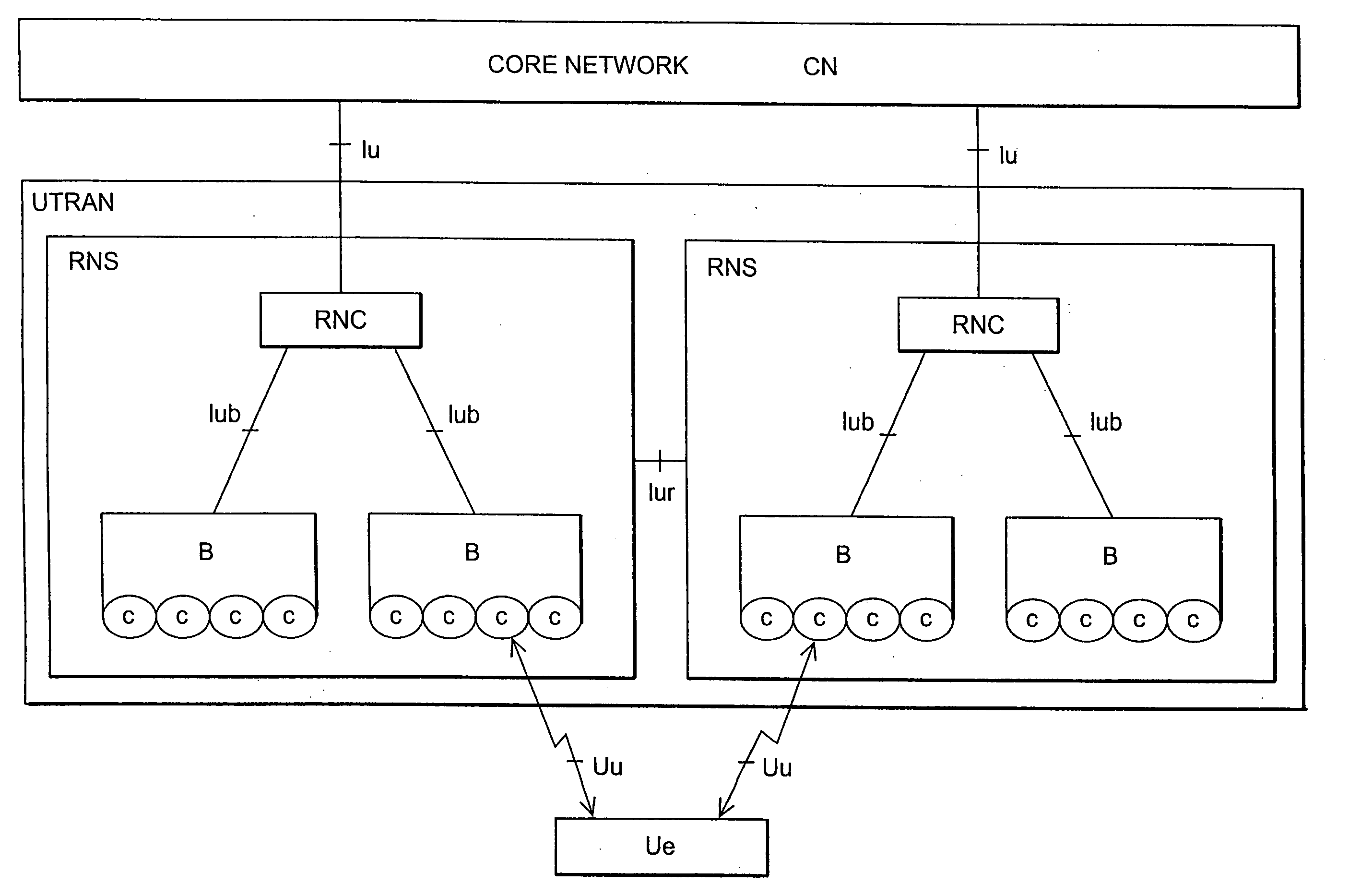
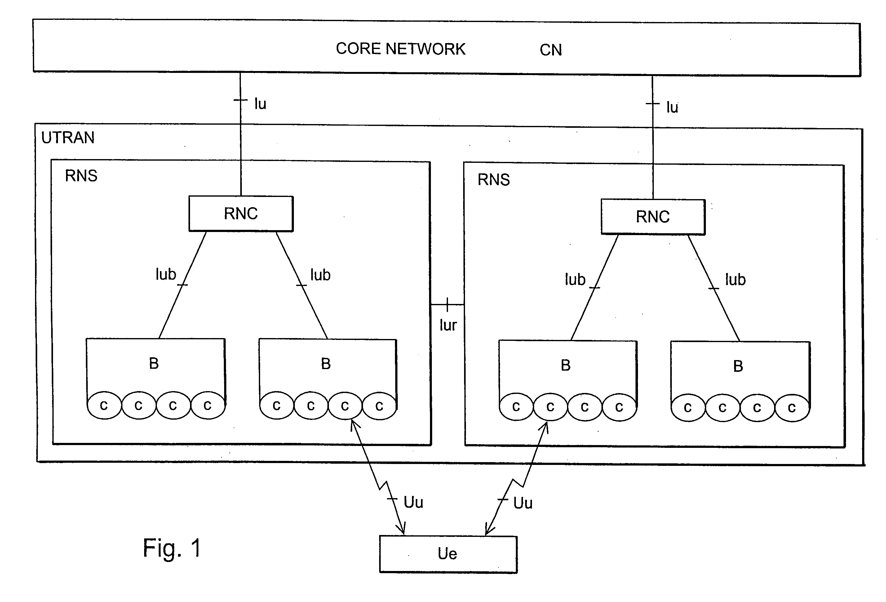
[0022]With reference to FIG. 1, a structure of a mobile telephone system is explained by way of example. The main parts of the mobile telephone system are core network CN, terrestrial radio access network of the mobile telephone system UTRAN (UMTS terrestrial radio access network) and user equipment UE. The interface between the CN and the UTRAN is called lu and the air interface between the UTRAN and the UE is called Uu.

[0023]The UTRAN comprises radio network subsystems RNS. The interface between the RNSs is called lur. Th...


PUM


Abstract

The invention relates to an interference cancellation method and a receiver including interference canceller for suppressing a narrow-band interference signal from a received signal, converter for performing an orthonormal conversion of the signal into subspace components of a desired subspace, a decoder connected operationally to the output of the interference canceller, in which decoder an estimate for the received signal is obtained. The output of the decoder is operationally connected to the interference canceller, and the converter is arranged to determine an estimate for narrow-band interference properties, in which determination the estimate obtained from the output of the decoder is subtracted from the received signal before the orthonormal conversion is performed. By using the determined estimate, the interference canceller is arranged to reduce effect of the subspace components including narrow-band interference signals from the received signal.

Description

[0001]This is a Continuation of PCT Application No. PCT / FI01 / 00115 which was filed on Feb. 8, 2001, which designated the U.S.FIELD OF THE INVENTION[0002]The invention relates to a receiver and a method of suppressing a narrow-band interference from a wide-band signal.BACKGROUND OF THE INVENTION[0003]Telecommunication connections are subject to various interferences. There are several reasons for interference. In telecommunication connections, the transmission path used for transmitting signals is known to cause interference to telecommunication. This occurs regardless of the physical form of the transmission path; whether the transmission path is, for instance, a radio link, an optical fibre or a copper cable. Particularly in radio telecommunication there are frequently situations where the quality of the transmission path varies from one connection to another and also during a connection.[0004]Radio path fading is a typical phenomenon that causes changes in a transmission channel. ...

Claims


Application Information

Patent Timeline
IPC IPC(8): H04J11/00H03K5/01H04B1/10H04B1/707
CPCH04B1/7107H04B1/7101H04B1/1036
Inventor TULINO, ANTONIA MARIA
Owner NOKIA CORP
Learn More