Two-piece interior trim retainer

a retainer and interior trim technology, applied in the direction of threaded fasteners, screw connections, hose connections, etc., can solve the problems of improper seated and secured fasteners to the sheet metal

Inactive Publication Date: 2006-10-03
NEWFREY
View PDF205 Cites 82 Cited by
  • Summary
  • Abstract
  • Description
  • Claims
  • Application Information

AI Technical Summary

Problems solved by technology

Due to slight misalignments, which can occur between the fasteners and their corresponding...

Method used


Image

  • Two-piece interior trim retainer
  • Two-piece interior trim retainer
  • Two-piece interior trim retainer

Examples


Embodiment Construction

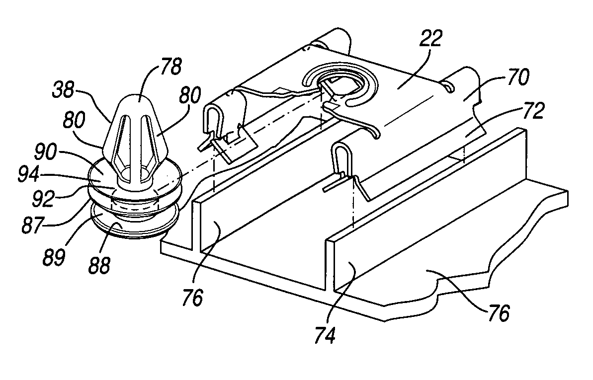
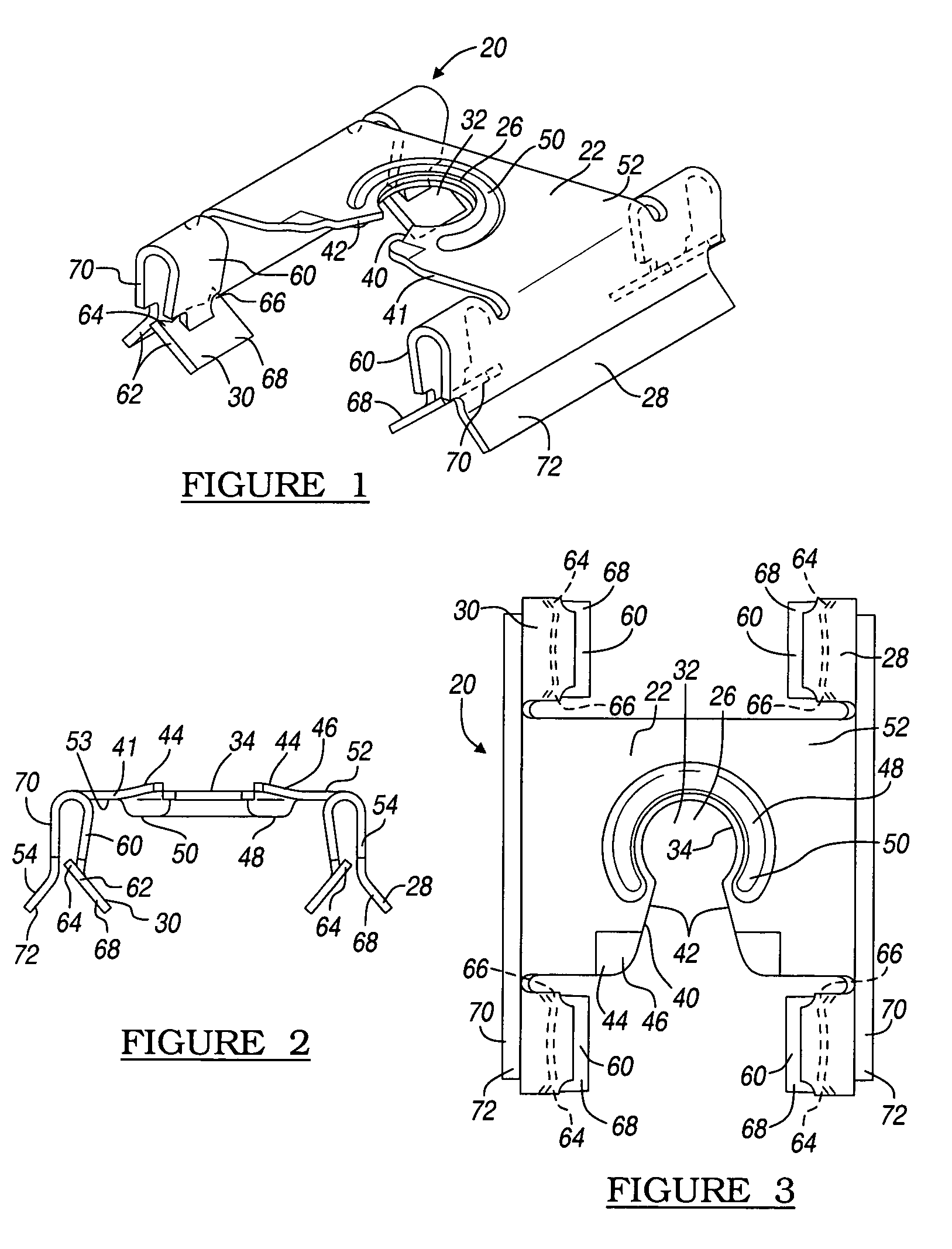
[0015]FIG. 1 represents a perspective view of the metal fastener 20 according to the teachings of the present invention. The fastener 20 has a generally planar body portion 22 which defines a coupling region 26. As described below, the coupling region 26 is configured to couple the metal fastener 22, a cylindrical fastener. The body 22 also has a pair of generally parallel coupling members 28 and 30 which are configured to couple the metal fastener 20 to a pair of generally parallel flanges (see FIG. 5).

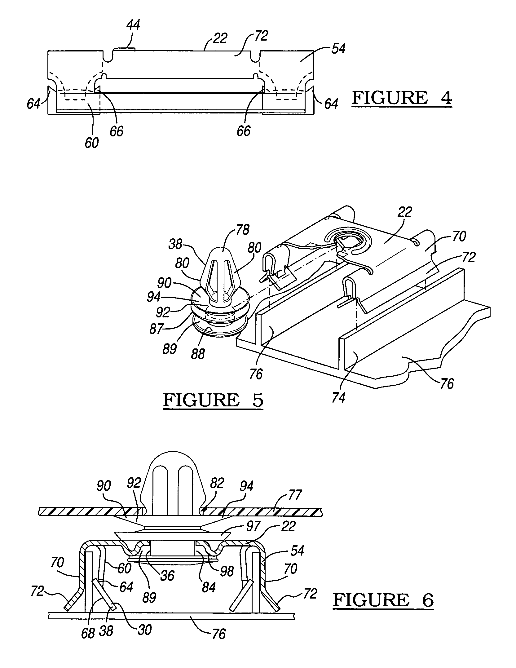
[0016]The body portion 22 defines the coupling portion 26 as an aperture 32. The aperture 32 defines an interior coupling surface 34 which functions to support a cylindrical mating surface 36 (see FIG. 5) of a second member 38 as described below. Defined by the body portion 22 and coupled to the aperture 32 is an insertion channel 40. The insertion channel 40 is defined on a distal end 41 of the body by a pair of angled walls 42. Defined on a first portion 44 of each of the angled wa...


PUM


Abstract

A resilient clip for engaging a structure and having a body portion with a pair of top flanges, a pair of fastening members and a pair of abutting flanges. Each of the fastening members has a base portion that is coupled to an associated one of the top flanges. Each of the abutting flanges has a locking fingers which engages the mounting structure. Finger flange portions are configured to engage a first side of a mounting flange on an interior trim component.

Description

TECHNICAL FIELD[0001]The present invention relates generally to resilient clip fasteners and more particularly to a resilient clip fastener that employs a two piece geometry to secure the body portion of the resilient clip to a structure. More specifically, the present invention relates to a resilient clip fastener having a construction that utilizes a cylindrical body portion which is coupled to a metal retainer having abutment flanges to couple of an attachment flange. The invention also relates to a resilient clip fastener having a construction that accounts in several manners for part-to-part variation between the structures that are to be fastened together.BACKGROUND OF THE INVENTION[0002]Many current vehicles employ resilient clips to secure various components to the vehicle body. One such application concerns interior panels that mount to the interior of the vehicle such as on the doors. Such panels serve not only to provide occupants with a convenient point to grasp during i...

Claims


Application Information

Patent Timeline
IPC IPC(8): B60R13/02F16B5/06F16B19/00F16B21/08F16B21/09
CPCF16B5/065F16B5/0657F16B21/082Y10T24/344Y10T24/307Y10T24/309Y10T24/30
Inventor GIBBONS, MATTHEW H.PILON, ROGER E.HIGGINS, LAWRENCE J.
Owner NEWFREY
Why Eureka
Try Eureka