
Overhead door drop stop

a technology for dropping stops and overhead doors, applied in door/window protective devices, wing accessories, door/window fittings, etc., can solve problems such as high cost, injury, or even death, and/or difficult installation without extensive modifications, and can not be easily modified

Inactive Publication Date: 2006-10-03
ENTERPRISE SAFETY PRODS I
View PDF20 Cites 16 Cited by
  • Summary
  • Abstract
  • Description
  • Claims
  • Application Information

AI Technical Summary

Benefits of technology

[0009]One object of the present invention is to prevent personal injury and / or damage caused by a falling door.
[0010]Another object of the present invention is to provide a door drop stop system which can be installed on any existing door with minimal modifications to the door system.
[0012]Another object of the present invention is to provide a door drop system which is very economical to purchase.
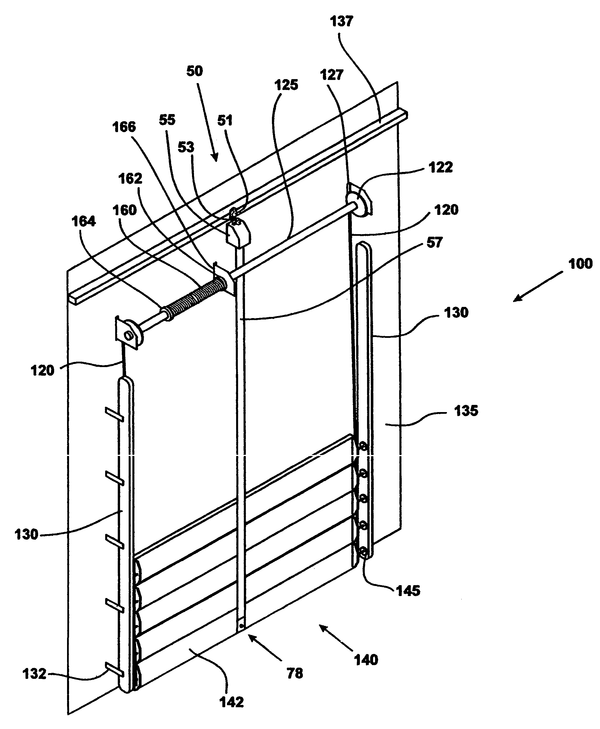
[0014]The present invention is a door drop stop system designed to require a minimal amount of time and modification to install in an existing door system. It is effective with all overhead doors which employ a central axle; such overhead doors are in widespread use in residential, commercial, and vehicular applications. In addition, other configurations of the door drop stop system are effective with slab doors, bifold doors, and rollup doors. The present invention will reduce or eliminate property damage and personal injury resulting from a failure of a component of the door or its counterbalance system.

Problems solved by technology

In the event any element of the aforementioned means breaks, the door can fall rapidly, causing possible property damage, injury, or even death.
Numerous methods have been employed to stop a door after such a failure, but they are either expensive, complicated, and / or difficult to install without extensive modifications.
It is also relatively complicated, comprising numerous moving parts which must interact in order to achieve its purpose.
While this invention could be utilized on an overhead type door, its installation would be difficult and time-consuming if performed on an existing door.
There is no provision to prevent the door from free-falling during opening or closing, if the counterbalance system fails.

Method used


Image

  • Overhead door drop stop
  • Overhead door drop stop
  • Overhead door drop stop

Examples


Embodiment Construction

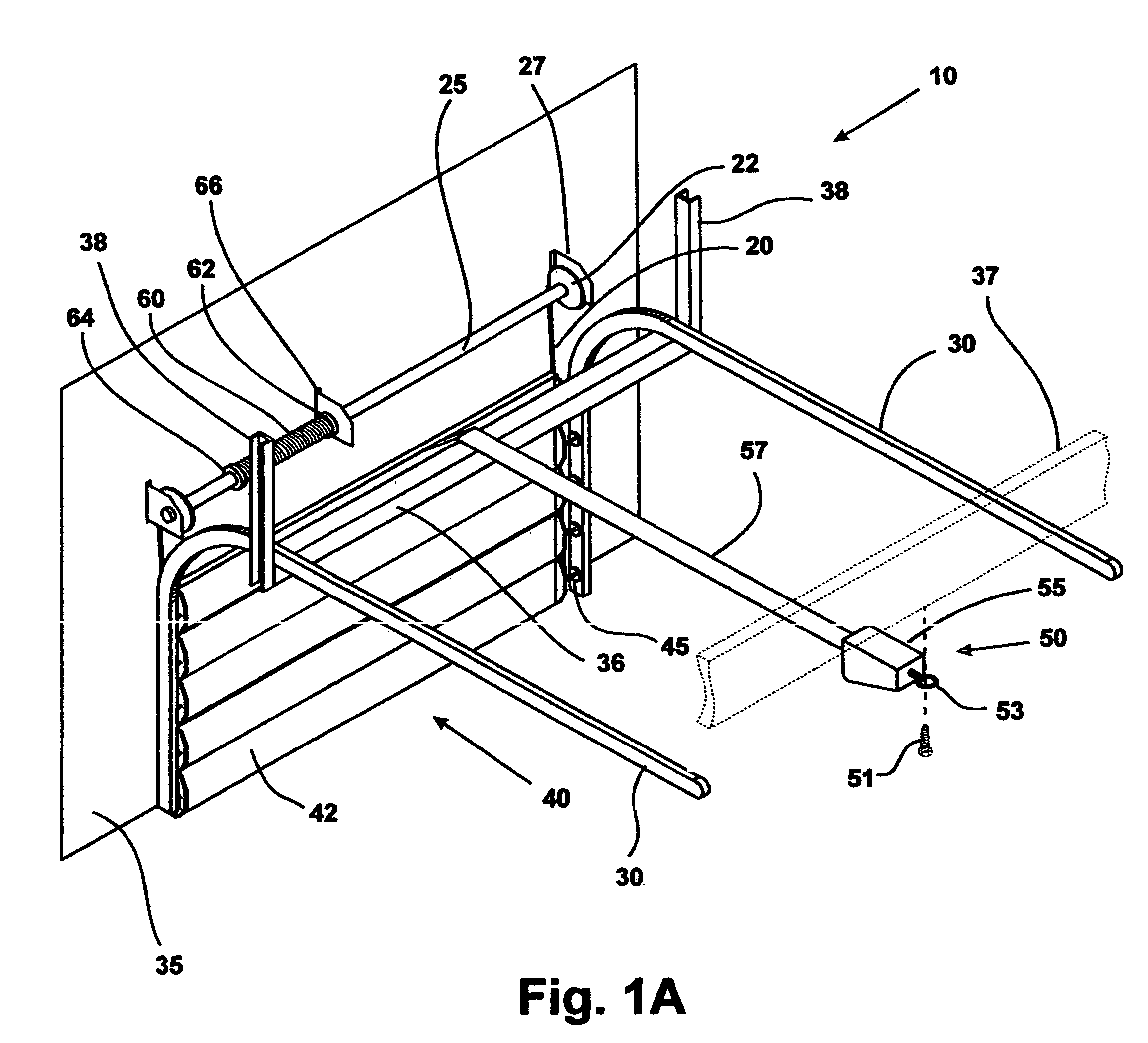
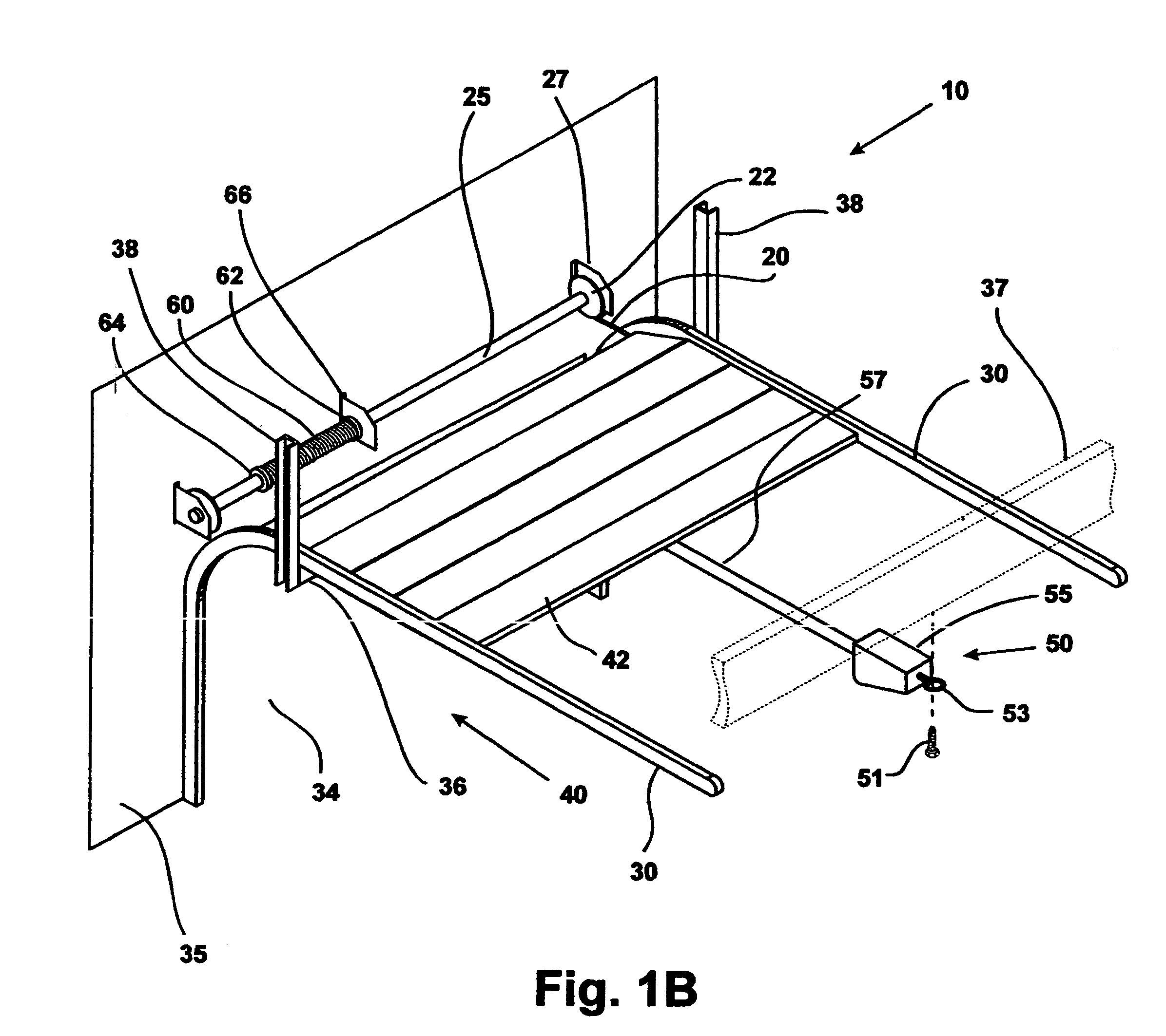
[0027]In accordance with the present invention, FIGS. 1A and 1B show a typical overhead door system with the door drop stop system installed, generally at 10.

[0028]The overhead door system is well known in the art. The following is a description of normal overhead door operation: In FIG. 1A, door 40 is shown in the closed position and comprises a plurality of door segments 42. Door 40 is heavy, and some means of counterbalancing that weight is needed, such as a torsion spring counterbalance. One end of torsion spring 60 is anchored to axle 25 by means of rotating spring mount 64. The other end of torsion spring 60 is anchored to center axle mount 66 by means of fixed spring mount 62. Mounted to the ends of axle 25 are pulley reels 22. Axle 25 and pulley reels 22 are free to rotate about their longitudinal axis and are mounted to wall 35 by outer axle mounts 27 and center axle mount 66. Cables 20 are affixed to both ends of bottom door segment 42, and to pulley reels 22.

[0029]With th...


PUM


Abstract

A door drop stop safety system which is adapted to be installed on existing building overhead doors which employ a central axle; slab doors, bifold doors, and rollup doors which contains structure for raising and lowering the the door including a rewind box including an inertia reel and a length of strap. The inertia reel allowing normal motion, but is adapted to lock as soon as a predetermined rate of rotation is reached due to the door beginning to free fall. The system includes structure means for mounting the rewind box on an existing door, including slab doors, bifold doors, and rollup doors.

Description

A. REFERENCE TO RELATED APPLICATION[0001]This application is a continuation of application Ser. No. 10 / 102,315 filed Mar. 21, 2002 now abandoned.I. FIELD OF THE INVENTION[0002]This invention relates to a stop mechanism, specifically to halt the sudden drop of an overhead or other vertically moving door in the event of a failure.II. BACKGROUND OF THE INVENTION[0003]A door may comprise a single heavy slab or a plurality of connected door segments, the sum of which are very heavy. Various means exist to aid in lifting the door, such as counterweights, torsion springs, and lifting cables. These aids effectively counteract the weight of the door which allows it to be easily lifted by manual or mechanical means. In the event any element of the aforementioned means breaks, the door can fall rapidly, causing possible property damage, injury, or even death.[0004]Numerous methods have been employed to stop a door after such a failure, but they are either expensive, complicated, and / or difficu...

Claims


Application Information

Patent Timeline
Patent Type & Authority Patents(United States)
IPC IPC(8): E05D13/00E05F11/54E05F15/20E06B9/84
CPCE05D13/003E05D13/1261E06B9/84E05Y2201/242E05Y2900/106E05Y2900/00
Inventor DAVID, KENNETH
Owner ENTERPRISE SAFETY PRODS I
Learn More