Device for installation and flow test of subsea completions

a technology for subsea completions and devices, applied in the direction of drilling pipes, wellbore/well accessories, sealing/packing, etc., can solve the problems of negating some of the cost savings available from riserless drilling, significantly affecting the profitability of individual wells, and affecting the overall installed cost of a well. , to achieve the effect of simple, reliable and rapid disconnection

Inactive Publication Date: 2006-10-03
FMC TECH INC
View PDF17 Cites 76 Cited by
  • Summary
  • Abstract
  • Description
  • Claims
  • Application Information

AI Technical Summary

Benefits of technology

[0009]The prior art arrangement requires the completions riser to be disconnected, followed by disconnection of the marine riser. The invention allows the installation string to be removed and the BOP rams to be closed above the flow package prior to commencement of well flow testing. This facilitates a simpler, more reliable and rapid disconnection at the marine riser in an emergency, e.g. when the installation vessel is driven off station.
[0015]The controls system thus reduces or even entirely eliminates the number of fluid lines in the service line umbilical. It may be used to control the following hydraulically actuated functions of the flow package:
[0022]The invention thus provides apparatus that eliminates the riser system during installation of a tubing hanger for any subsea completion design (e.g. dual bore conventional). This has the following benefits:
[0025]3. Elimination of the riser reduces project costs and potentially installation times and costs.
[0026]4. Coiled tubing operation could be performed during tubing hanger installation and thereby eliminate the use of an open water riser for coiled tubing operations during Christmas tree installation.

Problems solved by technology

The high pressure riser system represents a sigificant proportion of the installation equipment total cost and can, in the case of small projects, significantly affect the profitability of individual wells.
In the case of deepwater wells the time to run equipment can significantly affect the overall installed cost of a well.
Furthermore, although some investigations into riserless drilling of the well have been carried out, completion equipment currently in use requires a high pressure riser for instaltion of the tubing hanger.
This negates some of the cost savings available from riserless drilling.

Method used


Image

  • Device for installation and flow test of subsea completions
  • Device for installation and flow test of subsea completions
  • Device for installation and flow test of subsea completions

Examples


Embodiment Construction

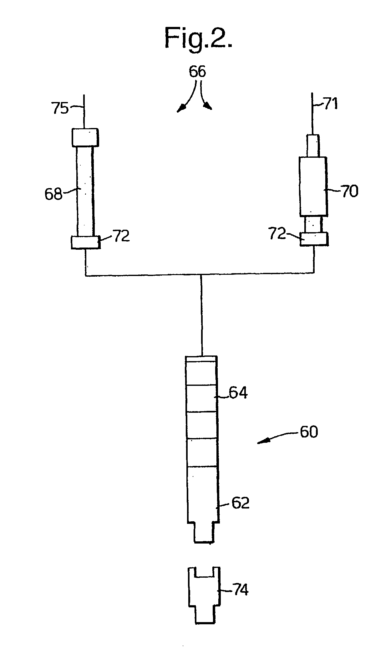
[0045]The overall landing string assembly shown in FIG. 2 has two major sections: a lower section 60 comprising a THRT 62 attached to the flow package 64; and interchangeable upper sections 66 comprising a wireline lubricator 68 and coiled tubing injector 70 as required. The flow control package 64 acts as a wireline or coiled tubing BOP, similar to a surface equivalent. A remotely operable latch unit 72 permits the upper section of the landing string to be unlocked and retrieved to the surface for change out of wireline tools and coiled tubing 71. The THRT 62 is engageable with a tubing hanger 74 for TH installation, completion testing and wireline / CT operations.

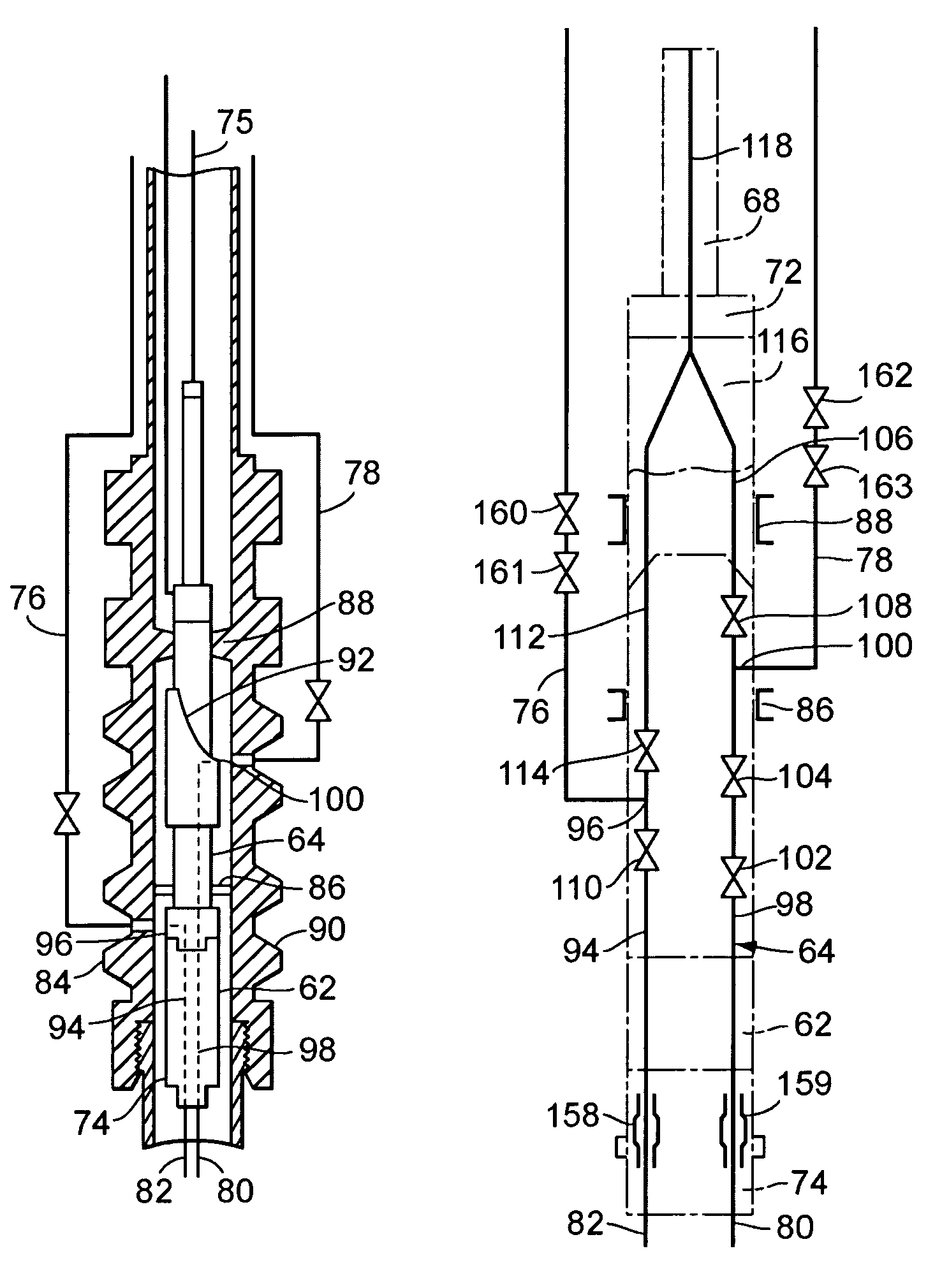
[0046]As shown in FIG. 3, the BOP choke lines 78 may serve as a flow path to the production bore 80 and the BOP kill lines 76 as a flow path to the annulus bore 82 of a dual, parallel bore completion. Valves in the flow control package 64 preferably control the flow, with the BOP 90 using its pipe rams 86 and annular seal b...


PUM


Abstract

A running string for a subsea completion comprises an upper section (70) which may be a coiled tubing (CT) injector unit as shown, or a wireline lubricator (FIG. 8). A lower section (60) provides wireline / CT access to production / annulus bores of a tubing hanger (not shown) attached to tubing hanger running tool (62). A flow package (64) in the lower section (60), together with BOP pipe rams (86) and annular seal (88), directs production and annulus fluid flows / pressures to the BOP choke / kill lines (78 / 76). The upper and lower sections allow installation and pressure / circulation testing of, and wireline / CT access to, a subsea completion, without the use of a high pressure riser.

Description

FIELD OF THE INVENTION[0001]This invention relates to installation and testing of completion components such as tubing and tubing hangers in a subsea well.INVENTION BACKGROUND[0002]Typically tubing hanger installation for either a conventional or horizontal subsea Christmas tree system utilises a riser as a method of lowering the tubing hanger to the wellhead / Christmas tree and as a means of transporting fluids to and from the wellbore. The riser also acts as a means of transporting wireline and coiled tubing from the surface to the desired location. The typical arrangement of installation equipment is as shown in FIGS. 1a–1d, with FIG. 1a showing a “conventional” completion and FIG. 1b a horizontal completion. In FIG. 1a, a BOP 10 is landed on and sealed to a wellhead 12. A marine riser 14 extends from the BOP 10 to a drilling vessel (not shown). The completion landing string comprising a tubing hanger (TH) 16 and associated tubing (not shown), tubing hanger running tool (THRT) 18 ...

Claims


Application Information

Patent Timeline
Patent Type & Authority Patents(United States)
IPC IPC(8): E21B17/01E21B33/043E21B43/013E21B33/035E21B33/076
CPCE21B33/035E21B33/076E21B33/043
Inventor GATHERAR, NICHOLASCOLLIE, GRAEME JOHN
Owner FMC TECH INC
Why Eureka
Try Eureka