Method and apparatus for removing cuttings from a deviated wellbore

a wellbore and cutting technology, applied in the direction of directional drilling, borehole/well accessories, construction, etc., can solve the problems of economic infeasibility of using jointed drill pipe, undesirable wiper trips, damage to the components of the drilling assembly,

Inactive Publication Date: 2006-10-03
HALLIBURTON ENERGY SERVICES INC
View PDF27 Cites 12 Cited by
  • Summary
  • Abstract
  • Description
  • Claims
  • Application Information

AI Technical Summary

Benefits of technology

[0013]U.S. Pat. No. 5,979,572 to Boyd et al., hereby incorporated herein by reference for all purposes, discloses a by-pass valving apparatus that enables removal of cuttings from a wellbore drilled using either conventional drill pipe or coiled tubing. The valving arrangement comprises an outer body with an inner spool mounted therein, motion control means to effect uni-directional rotation of the spool through pre-set positions, and a spring that biases the spool to a closed-off position. Fluid pumped through the drill string from the surface moves the spool against the spring, while simultaneously; the motion control means causes the spool to rotate to a pre-set position. Relieving the fluid pressure causes the spool to move axially with the spring and to rotate via the motion control means to the closed-off position. Subsequent pumping of fluid through the drill string causes the spool to move axially and to rotate to yet another pre-set position. In this way, the spool is selectively moved through a number of pre-set positions that close off flow, or direct fluid entirely or partially into the wellbore.

Problems solved by technology

During such drilling operations, it may be economically infeasible to use jointed drill pipe.
Wiper trips are undesirable because they consume valuable drilling time and can cause damage to the components of the drilling assembly 200, such as the drill bit 210.

Method used


Image

  • Method and apparatus for removing cuttings from a deviated wellbore
  • Method and apparatus for removing cuttings from a deviated wellbore
  • Method and apparatus for removing cuttings from a deviated wellbore

Examples


Embodiment Construction

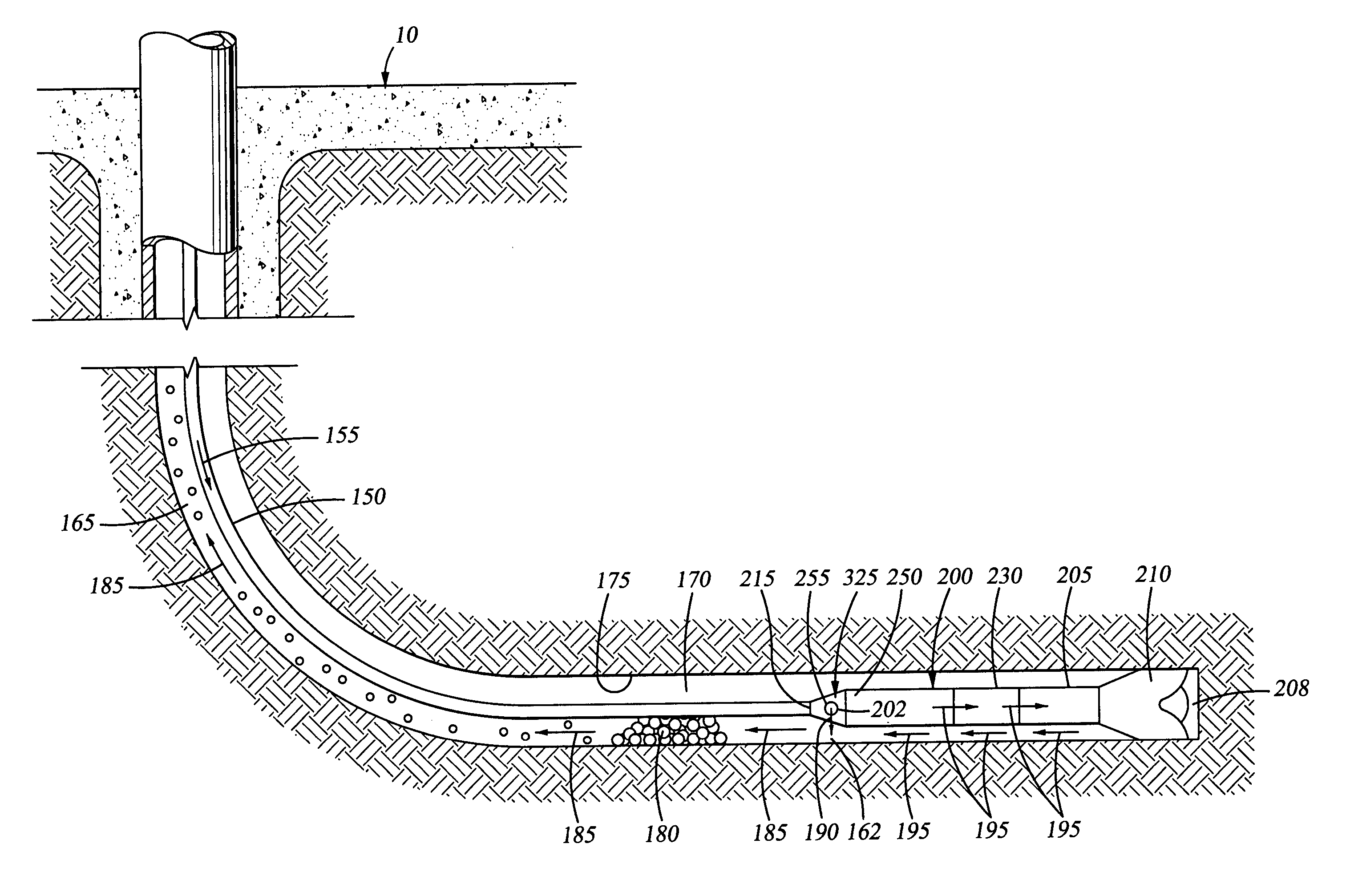
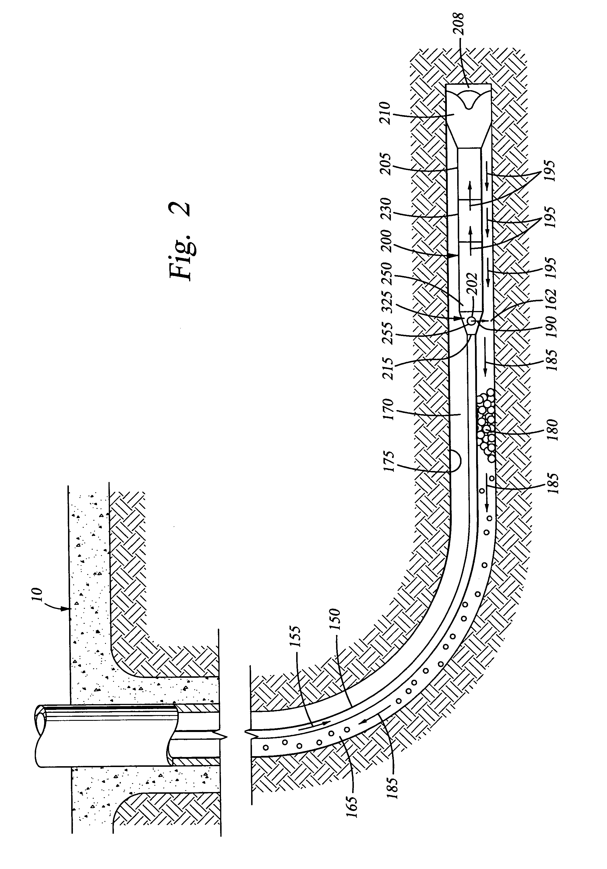
[0073]In one embodiment, the present invention comprises apparatus and methods for diverting drilling fluid into a wellbore annulus to continuously carry cuttings to the surface while drilling the wellbore. The present invention is particularly well suited for deviated wellbores that are drilled using non-rotating drill pipe, such as coiled tubing, where cuttings tend to accumulate in the wellbore annulus around the drill string as the wellbore is being drilled. A “deviated” wellbore, as used herein, indicates a wellbore that is substantially non-vertical, such that cuttings are likely to accumulate, such as wellbores having an angle greater than 30° from vertical.

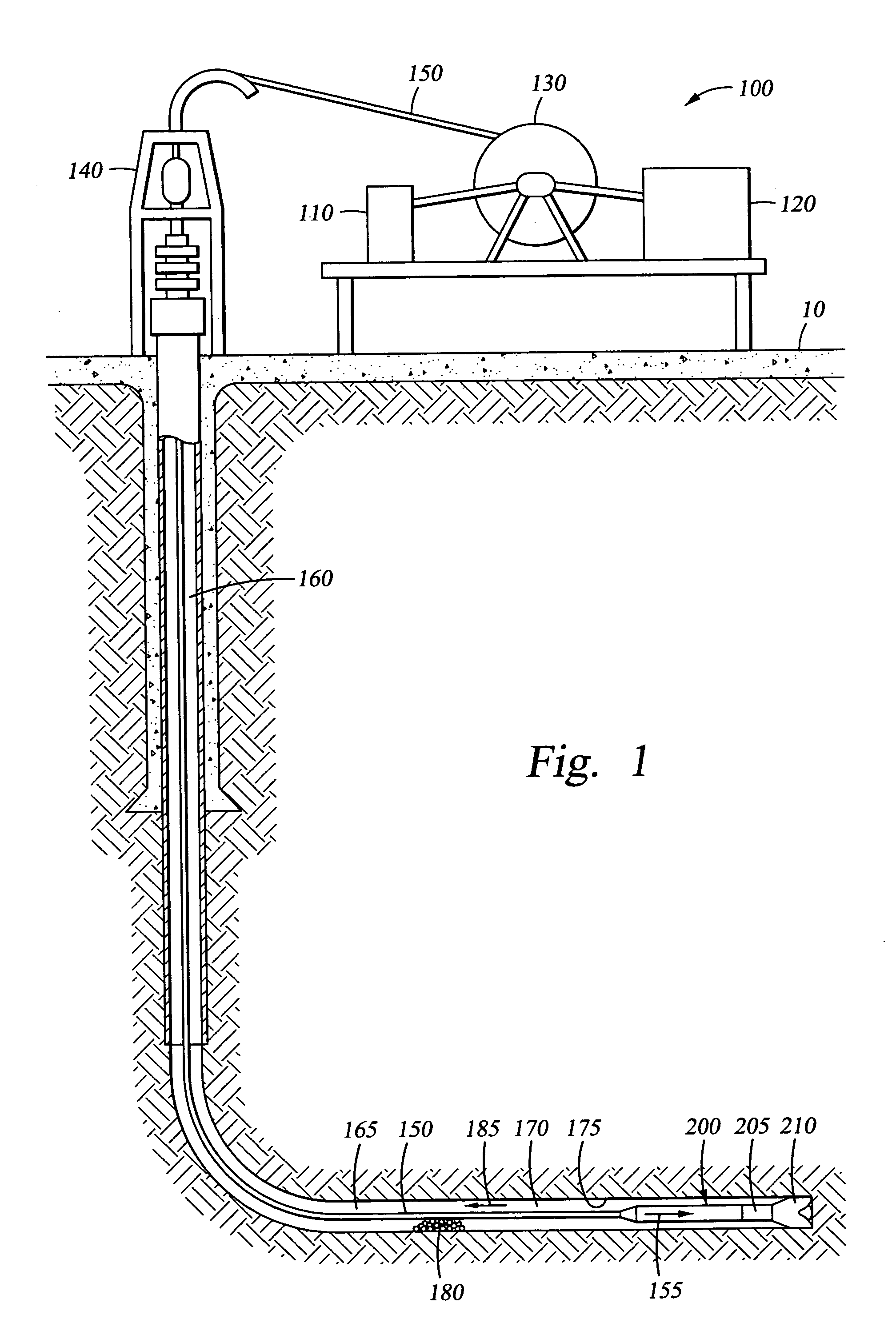
[0074]Referring again to FIG. 1, during a typical drilling operation, drilling fluid flows through the coiled tubing 150 and into the drilling assembly 200 along path 155 to power the drilling motor 205 and drill bit 210. After exiting the drill bit 210, the drilling fluid flows back to the surface 10 along path 185 throug...


PUM


Abstract

Apparatus and methods for diverting a portion of the drilling fluid that flows into a drilling assembly comprise diverting the drilling fluid into the annulus of a deviated wellbore at a flow rate corresponding to a velocity that is sufficient to transport cuttings to the surface while drilling progresses. The diverted drilling fluid is directed into the annulus at an angle to prevent erosion of the wellbore wall. The flow rate of the diverted drilling fluid is controlled to establish a fixed flow rate, or alternatively, a variable flow rate. Pressure is dissipated and fluid velocity is reduced as the diverted drilling fluid flows between a high fluid pressure within the drilling assembly to a lower pressure in the wellbore annulus.

Description

CROSS-REFERENCE TO RELATED APPLICATIONS[0001]The present application claims the benefit under 35 U.S.C. Section 119(e) of provisional application Ser. No. 60 / 416,020 filed Oct. 4, 2002, and entitled “Method and Apparatus for Removing Cuttings from a Deviated Wellbore”.STATEMENT REGARDING FEDERALLY SPONSORED RESEARCH OR DEVELOPMENT[0002]Not Applicable.BACKGROUND[0003]1. Field of the Invention[0004]The present invention relates generally to methods and apparatus for removing cuttings from a deviated wellbore, and more particularly, to methods and apparatus for diverting drilling fluid into a wellbore annulus to remove cuttings from a deviated wellbore as drilling progresses.[0005]2. Description of the Related Art[0006]Historically, oil and gas were produced from hydrocarbon formations by drilling a substantially vertical wellbore from a surface location above the formation to the desired hydrocarbon zone at some depth below the surface. Modern drilling technology and techniques allow ...

Claims


Application Information

Patent Timeline
Patent Type & Authority Patents(United States)
IPC IPC(8): E21B21/06E21BE21B21/10
CPCE21B21/103
Inventor EPPINK, JAY M.PHILLIPS, BRENT E.ESTEP, JAMES W.
Owner HALLIBURTON ENERGY SERVICES INC
Why Eureka
Try Eureka