
Light rope crown molding

a light rope and crown molding technology, applied in the direction of lighting support devices, lighting applications, ways, etc., can solve the problems of difficult installation and aesthetic unappealing, expensive methods of decorative, indirect interior or exterior lighting, and exposed wiring

Inactive Publication Date: 2006-10-03
LILLY DONALD W
View PDF7 Cites 40 Cited by
  • Summary
  • Abstract
  • Description
  • Claims
  • Application Information

AI Technical Summary

Benefits of technology

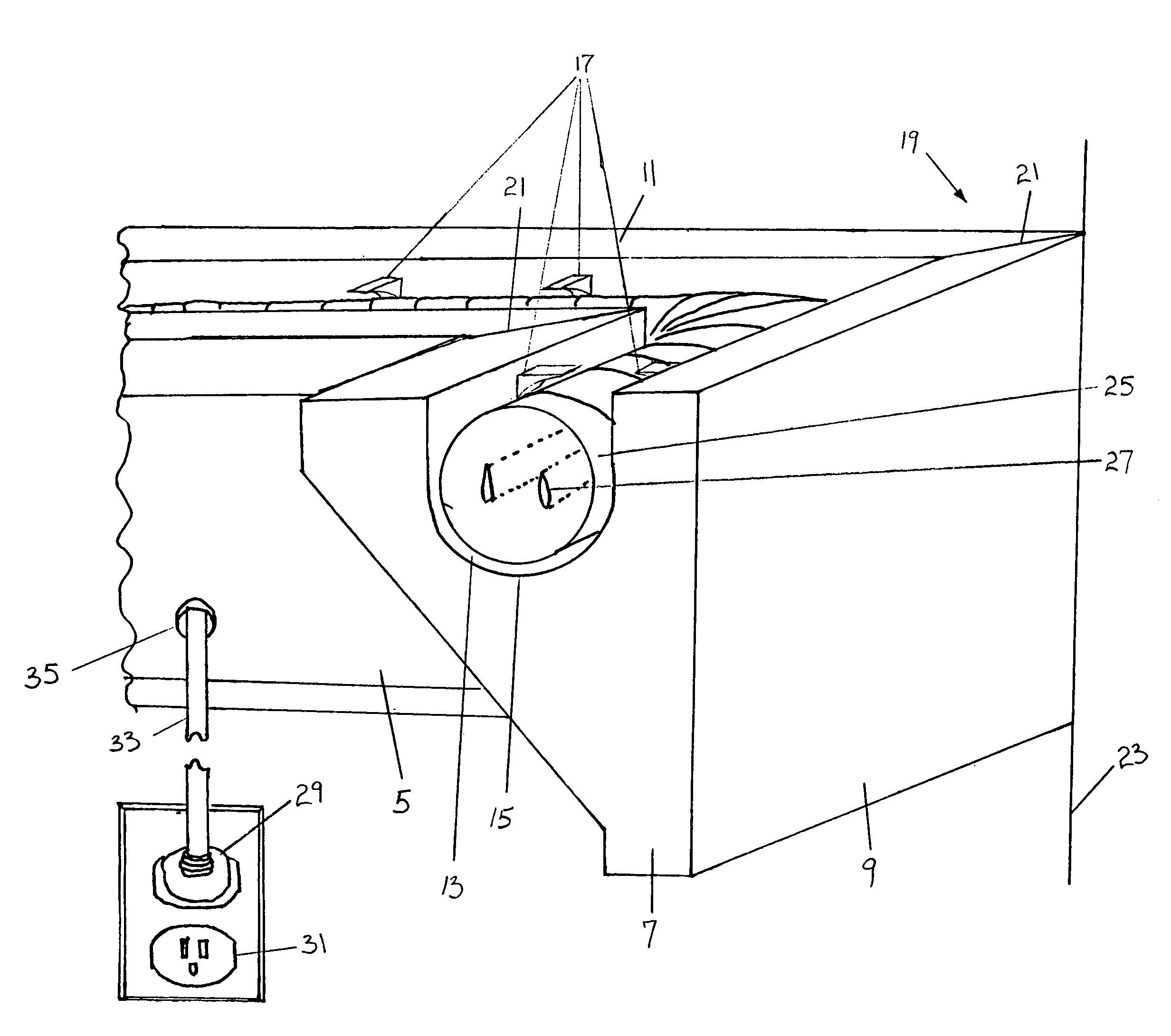
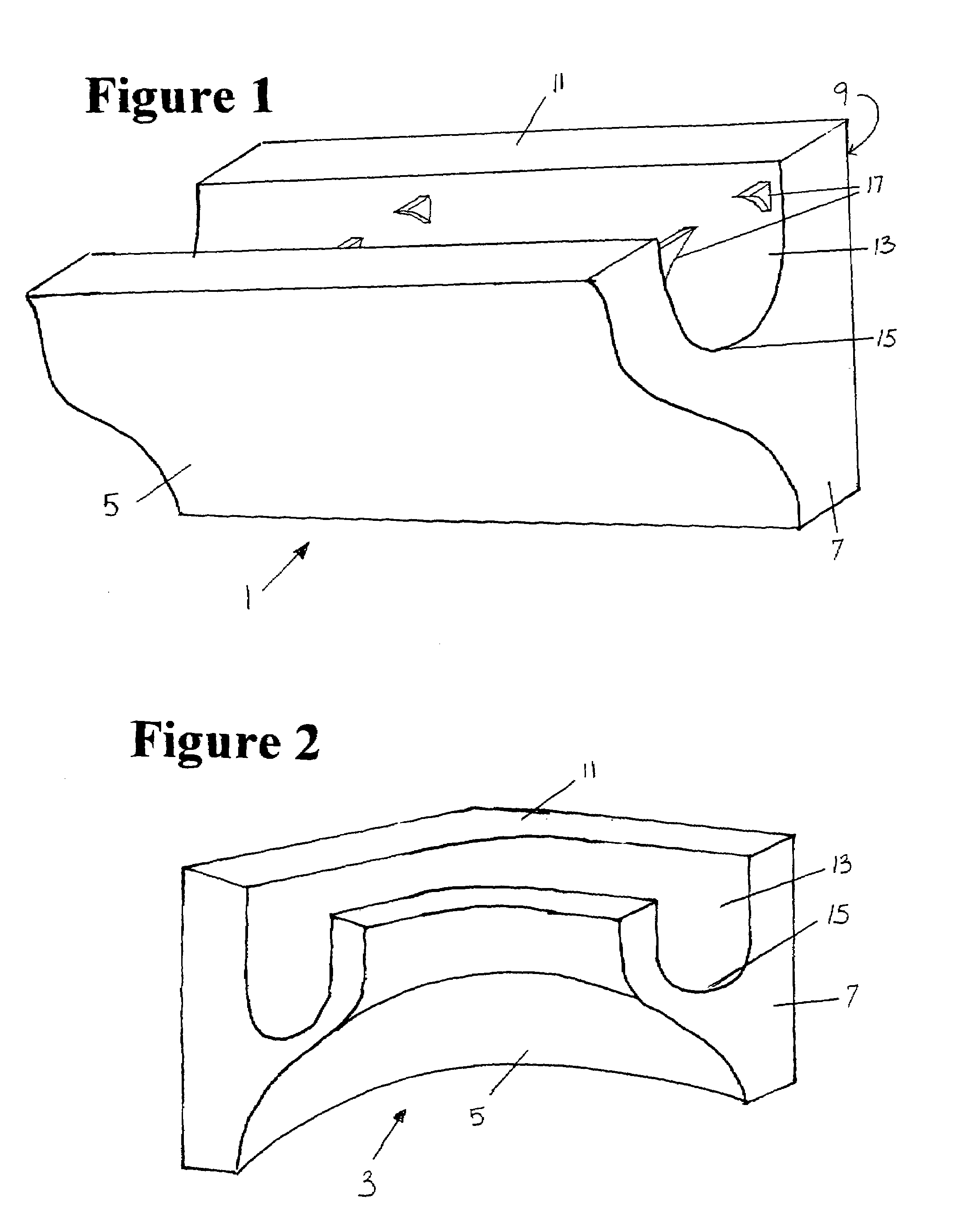
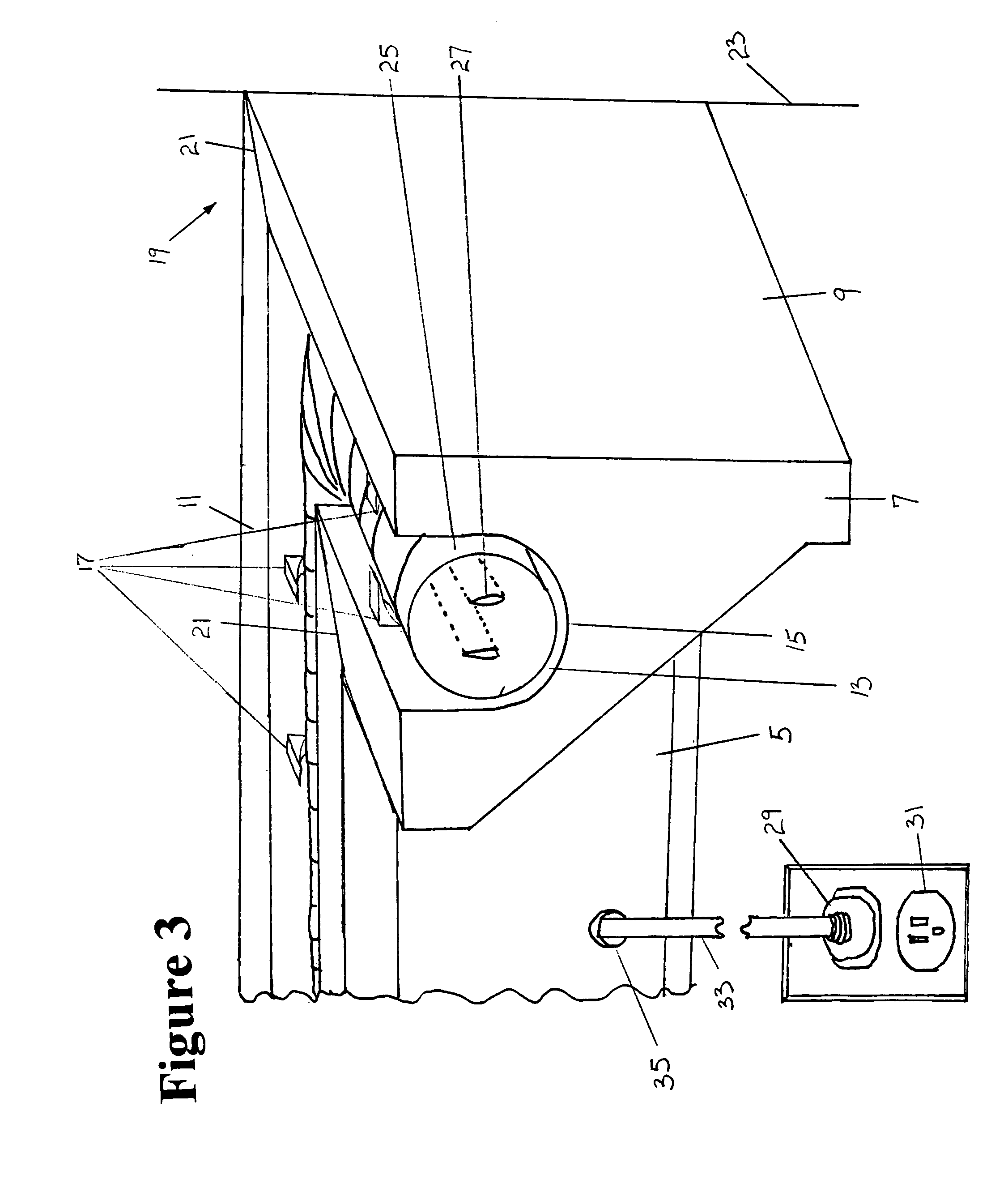
[0008]The crown molding of the present invention has a front surface that is designed based on user preference and room design. The separate pieces of crown molding can be straight, 90-degree corners, other angled corners, vertically or horizontally curved sections, or any other configuration. The ends of straight pieces of molding can have mitered corners to fit any angle or corner. Existing clips or tracks can be fixed into place on the molding or a notch can be cut in the molding to fit a light source, eliminating the need for separately molding clips or tracks. Each piece of crown molding can be of any length that is appropriate for a specific room. The front face can have many different configurations based on the decor and personal preference of the building owner. The crown molding is connected to a wall surface via a generally flat back surface. The front and back surfaces do not have to be the same height and varying heights allow light to be directed in desired directions. Screws, nails, glue or other attachment means connect the back surface to the wall or surface.
[0010]Protrusions located along the length of the crown molding groove form clips that allow a user to snap the light rope into place. The clips prevent the light rope from shifting or warping and prevent the light rope from snaking, elongating, warping or extending above the rim of the groove. Existing clips or grooves can be utilized as well.
[0013]Other embodiments of the present invention provide indirect illumination for alternative purposes. Decorative molding with grooves for light ropes or other light sources is used as complex crown molding with decorative relief. Decorative relief patterns are molded or cut into pieces of crown molding in the path of the indirect lighting coming from the light source. The indirect lighting creates patterns of shadows and light that are visually appealing.
[0014]In another embodiment, a rope light within the present crown molding may be attached below or along the bottom of existing crown molding to provide indirect lighting on the existing crown molding for aesthetic effect. The rope light may be contained in a smaller piece of material that is attached directly to the wall below the existing crown molding. The light cast by the light rope or other light source creates patterns of darkness and shadow for an appealing affect.

Problems solved by technology

Currently methods of decorative, indirect interior or exterior lighting are often expensive, difficult to install and aesthetically unappealing.
These systems often leave the wiring exposed and are not a visually attractive method of installing lighting.
Previous solutions to the need for indirect lighting involve complicated fluorescent lighting fixtures.
Fluorescent apparatus are limited by the characteristics of fluorescent lighting, because fluorescent bulbs are mass-produced in limited sizes and the bulbs are rigid.
Those considerations restrict the configurations available for decorative elements.
Fluorescent lamps are relatively fragile and require substantial space surrounding the bulbs.
Current methods of installing light ropes are inadequate due to the tendency of the light rope to sag in locations where there is no hook or other means of attachment to a surface.
Additionally, light ropes that are viewed directly are not appropriate for every decorating scheme.

Method used


Image

  • Light rope crown molding
  • Light rope crown molding
  • Light rope crown molding

Examples


Embodiment Construction

[0032]The present invention is an apparatus for providing indirect illumination to a building interior, exterior or fixtures using crown molding with specialized grooves for holding light ropes or other types of light sources. The invention generally consists of modular pieces of crown molding with an elongated groove in a top surface running parallel to a front surface. A light rope or other type of illumination is installed in the groove and provides indirect light on the wall, ceiling or other object above or below the light source. The direction and intensity of the indirect lighting is adjusted by altering the size and orientation of the groove and the shape of the molding. Clips hold the light rope or other source of illumination inside the groove. Existing clips or tracks can be used.

[0033]The crown molding of the present invention can be made from molded plastic, wood, aluminum, ceramic, foam composite materials, stone, plaster, metals, fiberglass, cast urethane or any other...


PUM


Abstract

The present invention is an apparatus for providing indirect illumination to a building interior or exterior using crown molding with specialized grooves for holding light ropes or other types of light sources. The invention generally consists of modular pieces of crown molding with an elongated groove in a top surface running parallel to the front surface. A light rope or other types of illumination are installed in the groove and provide indirect light on the wall, ceiling or other objects above the crown molding. Molding may also be used as picture frame and shelving accent lighting. Clips hold the light rope or other source of illumination inside the groove.

Description

[0001]This application claims the benefit of U.S. Provisional Application No. 60 / 505,109, filed Sep. 24, 2003.BACKGROUND OF THE INVENTION[0002]Currently methods of decorative, indirect interior or exterior lighting are often expensive, difficult to install and aesthetically unappealing. Methods exist for hanging strings of lights with hooks, clasps, and other similar devices. These systems often leave the wiring exposed and are not a visually attractive method of installing lighting.[0003]Previous solutions to the need for indirect lighting involve complicated fluorescent lighting fixtures. Fluorescent apparatus are limited by the characteristics of fluorescent lighting, because fluorescent bulbs are mass-produced in limited sizes and the bulbs are rigid. Those considerations restrict the configurations available for decorative elements. Fluorescent lamps are relatively fragile and require substantial space surrounding the bulbs. Space is needed to insert or replace the lamps after ...

Claims


Application Information

Patent Timeline
IPC IPC(8): F21S8/00
CPCF21V21/02F21S4/003F21V21/08F21W2111/027F21W2111/08F21S4/20
Inventor LILLY, DONALD W.
Owner LILLY DONALD W
Learn More