Methods and devices for sport ball training

a technology of sport ball and training method, applied in the direction of sports apparatus, etc., can solve the problems of difficult use or transportation of devices, difficult to master, and difficult for players to analyze and correct problems

Active Publication Date: 2006-10-03
PRO TENNIS TRAINING
View PDF27 Cites 35 Cited by
  • Summary
  • Abstract
  • Description
  • Claims
  • Application Information

AI Technical Summary

Benefits of technology

[0003]In one embodiment, a sport ball training device includes a support device and a ball sling with at least one resilient sling member which has a first end secured to the support device. The resilient sling member is confi

Problems solved by technology

This technique requires a specific stoke pattern to be developed which is difficult to master when a balls are delivered by a ball machine or an assistant because the balls are in constant motion and they typically land in different positions with varying characteristics of bounce.
When a mistake is made by a player or student attempting to learn a particular stroke technique, it can be difficult for the player to analyze and correct the problem due to the many inherent variables.
Some of

Method used


Image

  • Methods and devices for sport ball training
  • Methods and devices for sport ball training
  • Methods and devices for sport ball training

Examples


embodiment 110

[0051]The strain relief protects the tubular elastomeric material of the sling members 112 and 114 and prevents the metal wire from puncturing through the sling member tube when the ball sling 110 is tightly flexed. This embodiment 110 also has a sleeve 126, which is disposed tightly over the sling members 112 and 114 adjacent the retainer member 128. Sleeve 126 can be bonded in place or left unattached so the user can adjust the circumference of the loop 130 of the retainer member 128. The sleeve's 126 position is adjusted by stretching the ball sling 110, which reduces the diameter of the components and allows the sleeve 126 to be repositioned. In other embodiments, the ball sling 110 may be made from an elongate elastomeric member having a reinforcement layer, such as a braid, disposed over the elastomeric tubing. The upper ends of the sling members 112 and 114 may be secured to the support 16 by a barb 132 in a fashion similar to that discussed above and shown in FIG. 9.

embodiment 140

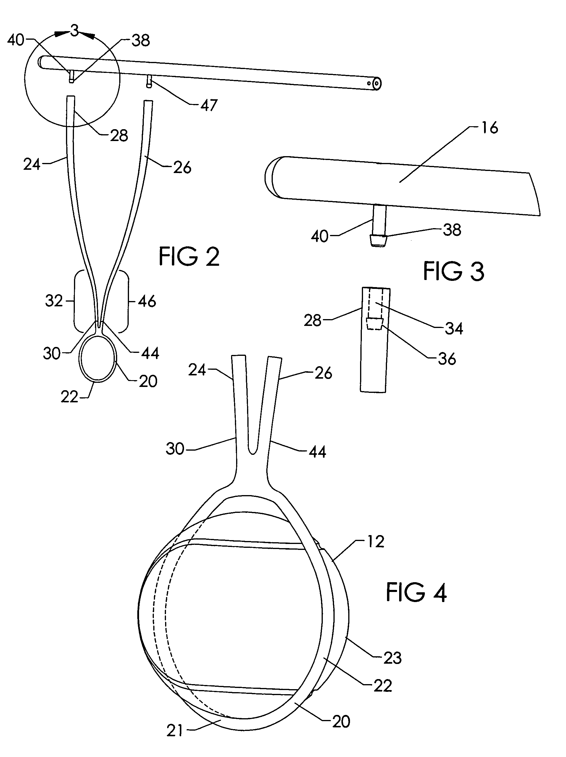
[0052]FIGS. 12 & 13 show another ball sling embodiment 140 that has sling members 142 and 144 constructed from metal spring wire. The lower portion or loop 146 of the sling members 142 and 144 are insert molded into an elastomeric loop 148 as shown by the dashed portion of the member in FIGS. 12 and 13. The spring metal sling members 142 and 144 of this embodiment are not coated or surrounded by any polymer or elastomeric material which provides a simple design that is suited mainly for low velocity impacts as it has no shock absorbing features other than the loop portion 148. The metal spring sling members 142 and 144 may be made of any suitable metal, including spring steel and superelastic alloys, such as nickel titanium alloys.

embodiment 150

[0053]FIGS. 14 and 15 show another ball sling embodiment 150. The spring metal sling members 152 and 154 of this embodiment are not coated or surrounded by any polymer or elastomeric material but shock absorbing sections 156 and 158 are incorporated in the sling members 152 and 154 in the form of a helical wind which reacts like an extension spring when exposed to tensile load. Striking balls at a high velocity may put high levels of stress on the ball sling 150. These embodiments, as well as others, may employ shock absorbing features to overcome this problem. This embodiment also has a rigid retainer member 160 with a loop 162 made from high impact plastic e.g. polycarbonate nylon molded over the spring metal sling members 152 and 154. Two or more inward radial protrusions 164 are attached to the rigid retainer member and are sized to make contact with and restrain a sport ball.

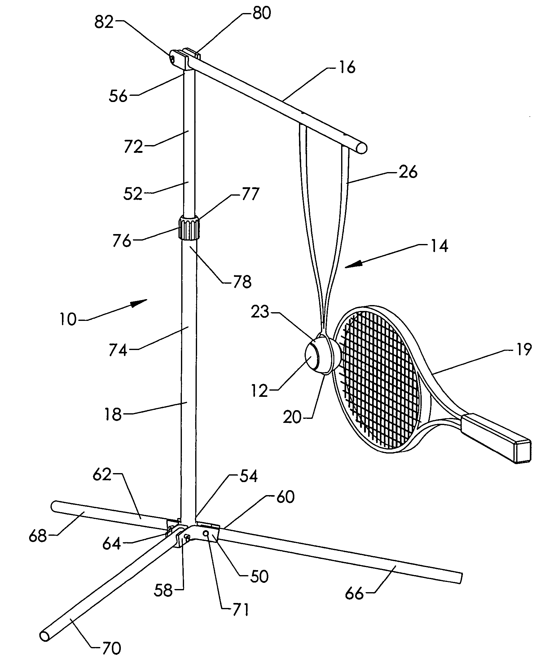
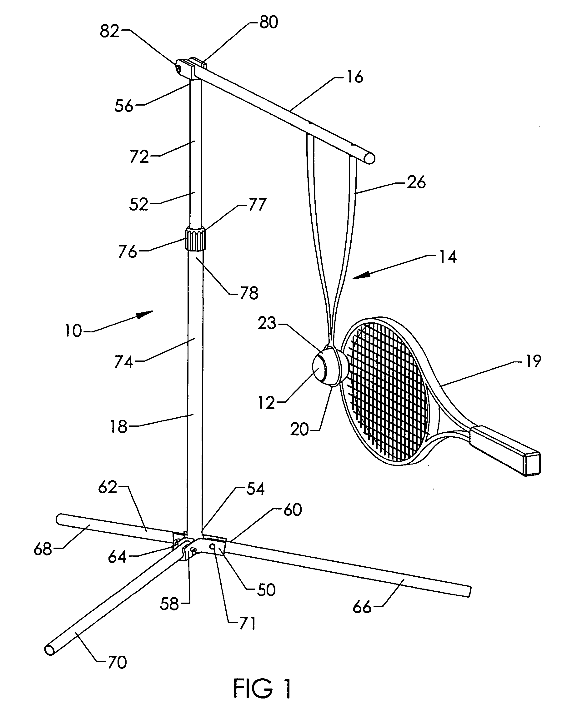
[0054]FIGS. 16–19 illustrate the support device 18 of the sport ball training device 10 in an exploded v...


PUM


Abstract

Sport ball training devices and methods for releasably holding a tennis ball or other sport ball at an appropriate height for the practice of striking the ball, either directly or indirectly with a racket or the like. An embodiment may have a support device with a base and an adjustable vertical tubular assembly for the support of a transverse arm from which a ball sling is suspended. A retainer member of the ball sling circumferentially holds a sport ball. An embodiment of the retainer member may be made from an elastometric material that lightly squeezes the ball with sufficient force to restrain it, but releases easily when the ball is hit so that the trajectory of the ball is not affected by the presence of the retainer member nor is the racquet significantly affected by the presence of the ball sling generally.

Description

CROSS REFERENCE TO RELATED APPLICATIONS[0001]This application claims priority under 35 U.S.C. section 119(e) from U.S. Provisional Patent Application Ser. No. 60 / 489,959, titled “SPORT BALL TRAINING DEVICE AND METHOD”, filed Jul. 23, 2003, by John L. Wardle and James M. Jensen and U.S. Provisional Patent Application Ser. No. 60 / 517,935, titled “SPORT BALL TRAINING DEVICE AND METHOD”, filed Nov. 5, 2003, by John L. Wardle and James M. Jensen, both of which are also incorporated by reference herein in their entirety.BACKGROUND[0002]Many sports require the hitting of a ball using different techniques to gain a competitive advantage in a game. For example in the sport of tennis the technique of making the ball spin as it travels through the air provides some distinct advantages. One ground stoke technique is that of hitting a ball with top spin in which the ball can driven through the air at a high velocity and still remain in play due to the curved flight path that the ball takes. This...

Claims


Application Information

Patent Timeline
IPC IPC(8): A63B69/38A63BA63B69/00
CPCA63B69/38A63B69/0079
Inventor WARDLE, JOHN L.JENSEN, JAMES M.
Owner PRO TENNIS TRAINING
Why Eureka
Try Eureka