
Electric separator with a rinsing cleaning system

a technology of cleaning system and separator, which is applied in the direction of electrode cleaning, electrostatic separation, coupling device connection, etc., can solve the problems of inability to clean the separator for a long time, and inability to effectively remove hardened deposits. to achieve the effect of reliable electrode cleaning

Inactive Publication Date: 2006-10-03
HENGST WALTER
View PDF35 Cites 17 Cited by
  • Summary
  • Abstract
  • Description
  • Claims
  • Application Information

AI Technical Summary

Benefits of technology

[0007]An aspect of the present invention is to improve a generic electric separator so that it renders possible a reliable electrode cleaning.
[0010]Advantageously, oil can be used as the fluid for cleaning the electrode surfaces, in particular oil that is taken from the oil circuit of the internal combustion engine. Although the electric separator is used to remove oil from the airflow, surprisingly and unexpectedly the additional introduction of oil of all things into the airflow is expedient, namely to clean the electrode surface because in this manner the expense for operating the electric separator can be kept relatively low compared to the requirement to use a special cleaning fluid and to stock the same and regularly refill it. Moreover, because good cleaning results can be achieved when oil is used as a rinsing fluid, evidently a high affinity exists to the deposits likewise originating from the oil, so that oil as a rinsing fluid picks up and carries away the deposits particularly well when the oil runs along the electrode surface.
[0012]The spray jet of the injection device can be advantageously directed at the wall of the electrode, thereby either the spray jet as a high-pressure jet can render possible an additional reinforcement of the cleaning performance. Due to the atomization effect that may possibly occur thereby, in these cases it can be provided to carry out such an injection operation only when the air speed in the electric separator is low. In this way the tendency of the air jet to entrain atomized oil particles during the injection operation is particularly slight, so that the separation performance of the electric separator is not inadmissibly impaired through the injection operation of the cleaning fluid.
[0013]Alternatively, it can be provided to direct the spray jet of the injection device tangentially at the wall of the electrode. In this way, a low-atomization spray surge is rendered possible which primarily serves to rinse and wet the electrode surface and renders possible at the most to a secondary extent a cleaning effect through the mechanical pressure of the spray surge.
[0014]Advantageously, a circuit can be provided that ensures an actuation of the injection device merely intermittently. While a continuous rinsing of the electrode surface is fundamentally conceivable, which would reliably rule out the deposit of particles on the electrode surface, it can be advantageously provided to carry out the cleaning only under certain operating conditions of the internal combustion engine. In this manner it can be reliably ensured that, e.g., oil does not reach the electrode surface at high engine speeds and accordingly high flow speeds of the air in the separator, which oil would otherwise be entrained due to the high air speed and would impair the separator performance of the electric separator.

Problems solved by technology

If one or both electrodes of the separator are to be freed from impurities adhering, a problem can exist that when mechanical cleaning installations are used, it is not possible to effectively remove hardened deposits.
Since the mechanical cleaning installations are operated intermittently, depending on the operating mode of the internal combustion engine, an interval between two cleaning operations can be so great that the deposits in the separator harden in the above-mentioned disadvantageous manner.

Method used


Image

  • Electric separator with a rinsing cleaning system
  • Electric separator with a rinsing cleaning system
  • Electric separator with a rinsing cleaning system

Examples


Embodiment Construction

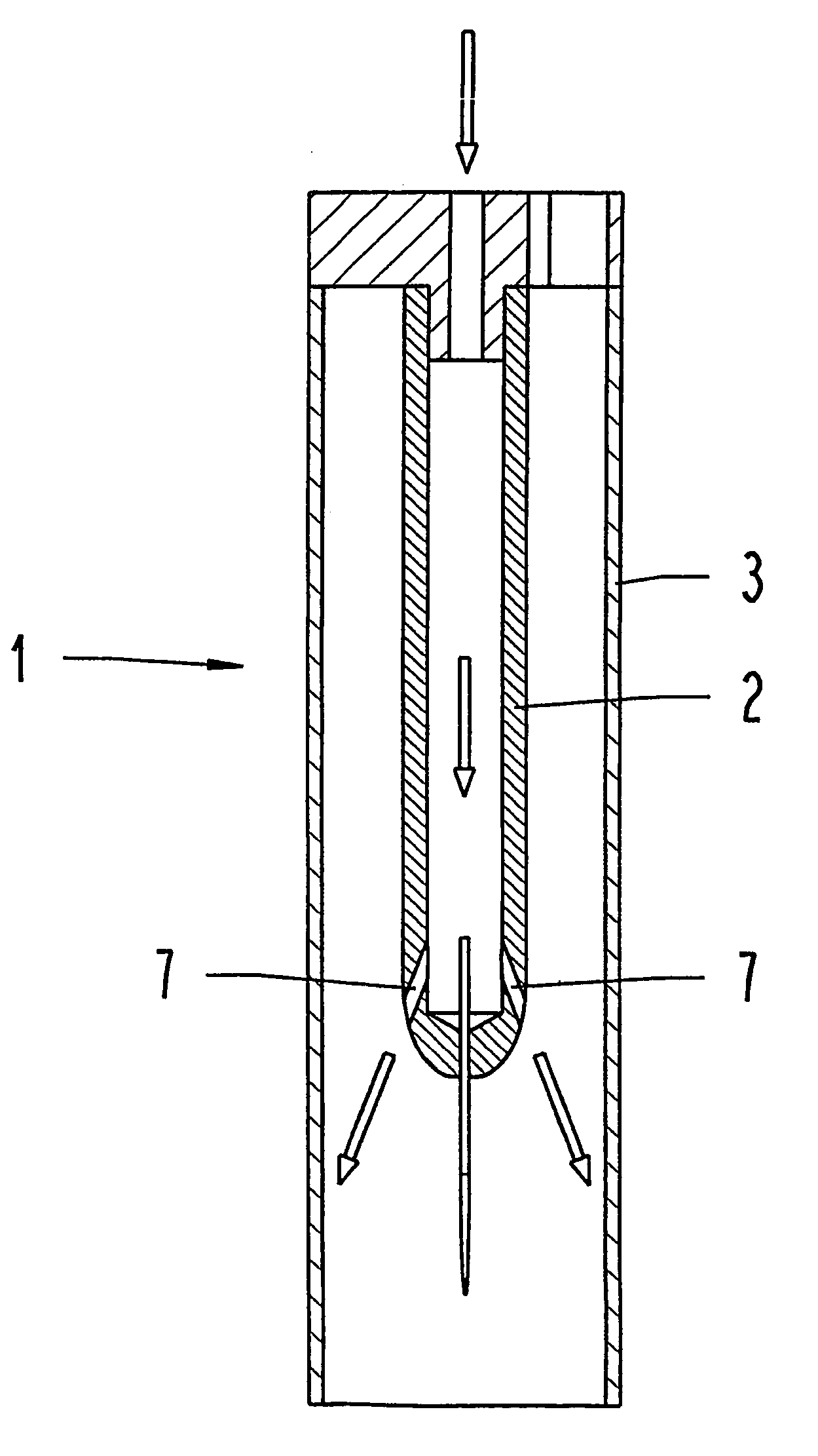
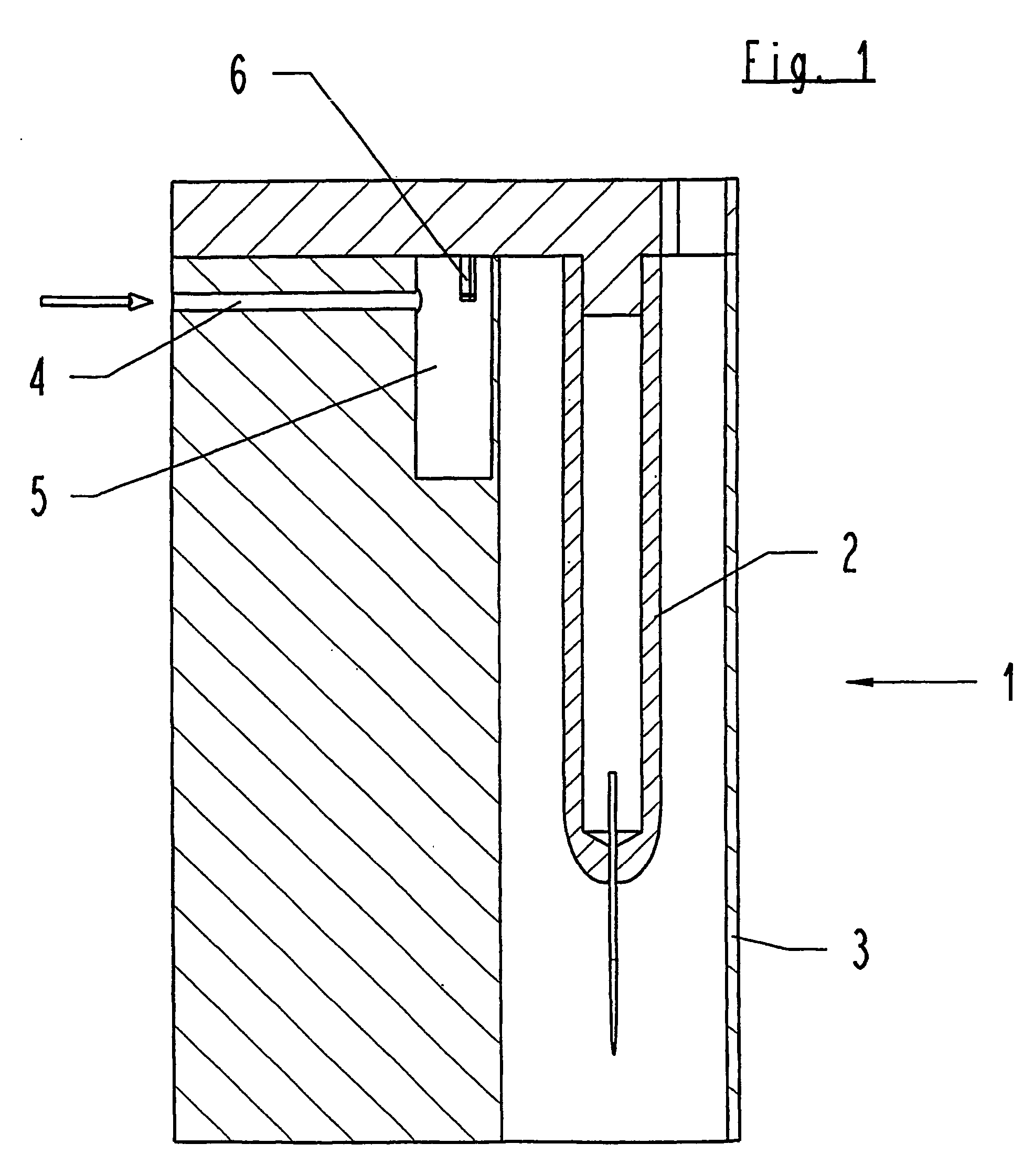
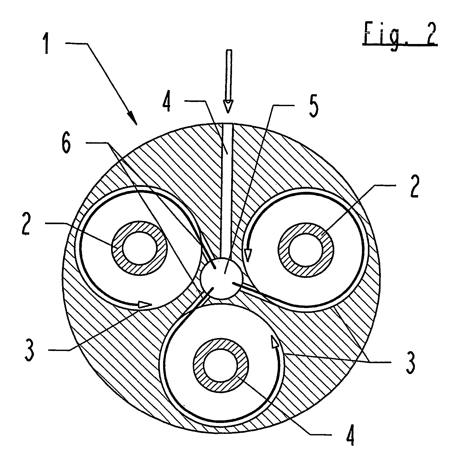
[0030]In FIG. 1, numeral 1 designates in general an electric separator that is arranged in the airflow of the crankcase ventilator of an internal combustion engine. As can be seen in particular from FIGS. 2 and 3, the separator 1 features three separator chambers in which respectively one emission electrode 2 is arranged and in which the tubular housing surface forms a cylindrical collecting electrode 3.

[0031]Oil reaches a distributor bore 5 via a supply line 4, and injection channels 6 lead tangentially from this distributor bore 5 to the collecting electrodes 3. As indicated by the arrows shown in FIGS. 2 and 3, the oil runs in a helical manner downwards on the inner surface of the collecting electrode 3, whereby it is provided in the exemplary embodiment shown that the assembly position according to FIGS. 1 and 3 is oriented with the free end of the emission electrode 2 pointing downwards. Assisted by gravity, the cleaning fluid, in the present case oil from the crankcase of the ...


PUM


Abstract

Electric oil separator that separates oil from an airflow of a ventilator. The separator includes an emission electrode and a collecting electrode. Moreover, the separator includes an injection device structured and arranged to inject oil as a cleaning fluid onto at least one of the emission electrode and the collecting electrode, so as to inject oil obliquely to a longitudinal axis of the collecting electrode.

Description

CROSS-REFERENCE TO RELATED APPLICATIONS[0001]The present application is a Continuation of International Application No. PCT / DE2003 / 002306, filed Jul. 9, 2003 and claims priority of German Patent Application No. 202 11 439.2, filed on Jul. 12, 2002. Moreover, the disclosure of International Patent Application No. PCT / DE2003 / 002306, filed Jul. 9, 2003 is expressly incorporated by reference herein in its entirety.BACKGROUND OF THE INVENTION[0002]1. Field of the Invention[0003]The invention relates to an electric separator for separating oil from an airflow of a crankcase ventilator of an internal combustion engine, with an emission electrode and with a collecting electrode.[0004]2. Discussion of Background Information[0005]A generic electric separator is known from DE-U-299 053 02.[0006]If one or both electrodes of the separator are to be freed from impurities adhering, a problem can exist that when mechanical cleaning installations are used, it is not possible to effectively remove ha...

Claims


Application Information

Patent Timeline
Patent Type & Authority Patents(United States)
IPC IPC(8): B03C3/78F01M13/04F02B77/04H01R13/70
CPCB03C3/78F01M13/04F02B77/04F01M2013/0427F01M2013/0466H01R13/70
Inventor AHLBORN, STEPHANBAUMANN, DIETERBATRAM, BERNHARD
Owner HENGST WALTER
Learn More