Stitched pole write element with a T-shaped pole tip portion

Inactive Publication Date: 2006-10-03
WESTERN DIGITAL TECH INC
View PDF6 Cites 163 Cited by
  • Summary
  • Abstract
  • Description
  • Claims
  • Application Information

AI Technical Summary

Benefits of technology

[0012]The pole tip portion includes three segments that define the T-shape; a nose segment, a wing segment, and a transition segment disposed between the nose and wing segments. The nose segment has a first width defined between two sidewalls that in some embodiments are substantially parallel. The nose segment has a nose length that in some embodiments is less than the zero throat depth.
[0013]The wing segment is recessed from the air bearing surface by more than the P3R depth and in some embodiments the wing segment begins at a depth greater than the zero throat depth. The wing segment has a second width, greater than the first width, also defined between two sidewalls. In some embodiments the sidewalls of the wing segment are substantially parallel, while in other embodiments the sidewalls diverge from one another such that the second width increases with depth from the air bearing surface.
[0014]The transition segment has a first end joined to the nose segment, a second end joined to the wing segment, and a variable third width that is less than the second width of the wing segment. The third width, as measured

Problems solved by technology

This magnetic flux leakage creates an undesirable effect commonly known as “side writing.” In essence, side writing is the tendency of the write element to influence the magnetic disk on

Method used


Image

  • Stitched pole write element with a T-shaped pole tip portion
  • Stitched pole write element with a T-shaped pole tip portion
  • Stitched pole write element with a T-shaped pole tip portion

Examples


Example

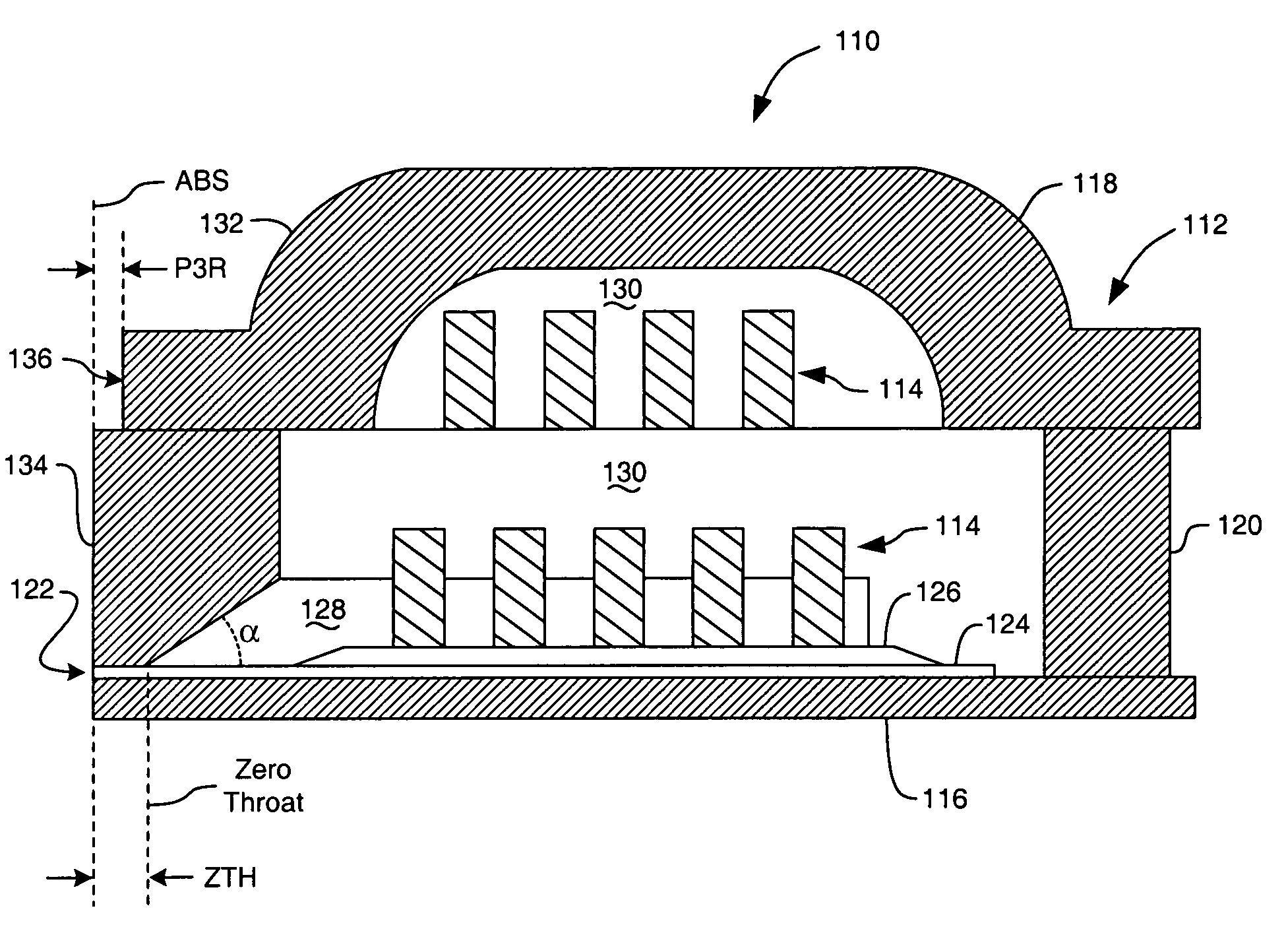
[0027]The present invention provides an improved design for a pole tip portion of an upper pole of a stitched pole write element. The improved pole tip portion is T-shaped such that the bottom of the “T” forms a narrow nose segment at the ABS, while the cross-bar top of the “T,” termed a wing segment, provides a greater stitched area between the pole tip portion and the yoke portion. A transition segment extends between the nose segment and the wing segment. The T-shaped pole tip portion does not widen significantly until after a distance, P3R, to minimize side writing.

[0028]FIG. 5A shows a pole tip portion 58 of the prior art compared to two exemplary pole tip portions 100, 102 of the invention (FIGS. 5B and 5C). Each exemplary pole tip portion 100, 102 includes a nose segment 104, a wing segment 106, and a transition segment 108 between the nose and wing segments 104, 106. It can be seen from FIGS. 5B and 5C that the nose segment 104 extends from the ABS to a depth termed the “nos...


PUM


Abstract

A T-shaped pole tip portion of an upper pole of a write element for a magnetic disk drive is provided. One end of the pole tip portion, constituting the bottom of the “T,” forms a narrow nose segment at an air bearing surface, while a wing segment at the opposite end of the pole tip portion constitutes the cross-bar top of the “T.” A transition segment extends between the nose segment and the wing segment. A yoke portion of the upper pole includes a surface that is parallel to the air bearing surface and recessed therefrom by a P3R depth. The transition segment does not widen significantly until after the P3R depth, accordingly, the wing segment is recessed from the air bearing surface by more than the P3R depth.

Description

BACKGROUND OF THE INVENTION[0001]1. Field of the Invention[0002]The present invention relates generally to the field of magnetic disk drives, and more particularly to an apparatus for writing data to a magnetic disk.[0003]2. Description of the Prior Art[0004]Magnetic disk drives are used to store and retrieve data for digital electronic apparatuses such as computers. In FIGS. 1 and 2, a magnetic disk data storage system 10 includes a sealed enclosure 12, a disk drive motor 14, and a magnetic disk, or media, 16 supported for rotation by a drive spindle 17 of motor 14. Also included are an actuator 18 and an arm 20 attached to an actuator spindle 21 of actuator 18. A suspension 22 is coupled at one end to the arm 20 and at another end to a read / write head 24. The suspension 22 and the read / write head 24 are commonly collectively referred to as a head gimbal assembly (HGA). The read / write head 24 typically includes an inductive write element and a magnetoresistive read element that are...

Claims


Application Information

Patent Timeline
IPC IPC(8): G11B5/147
CPCG11B5/3116G11B5/3113G11B5/3133
Inventor HE, QINGKAMIMURA, HIROHIKOOTANI, SHUHEIWANG, YUGANGSEAGLE, DAVID J.
Owner WESTERN DIGITAL TECH INC
Why Eureka
Try Eureka