Built-in self-test circuit
a self-testing, built-in technology, applied in the field of built-in self-testing circuits, can solve problems such as the increase of the chip area, and achieve the effect of reducing the number of 1-bit comparators and reducing the size (the number of gates)
- Summary
- Abstract
- Description
- Claims
- Application Information
AI Technical Summary
Benefits of technology
Problems solved by technology
Method used
Image

Examples
first embodiment
[0033]FIG. 3 shows a block diagram of the configuration of a RAMBIST circuit according to the present invention. As shown in FIG. 3, the RAMBIST circuit comprises a signature analyzer 101, a data generator 3, a controller 104, and a bit changer 6 provided with selectors.
[0034]Data output bits, A[0] to A[n−1], of a RAM macro 2 as a circuit to be tested are grouped by, for example, 2 bits though not particularly limited, and divided into n / 2 groups. The bit changer 6 has n / 2 selectors 61, each of which individually corresponds to each group of the data output bits. In other words, each selector 61 selects either one of two data output bits in each group for the data output bits.
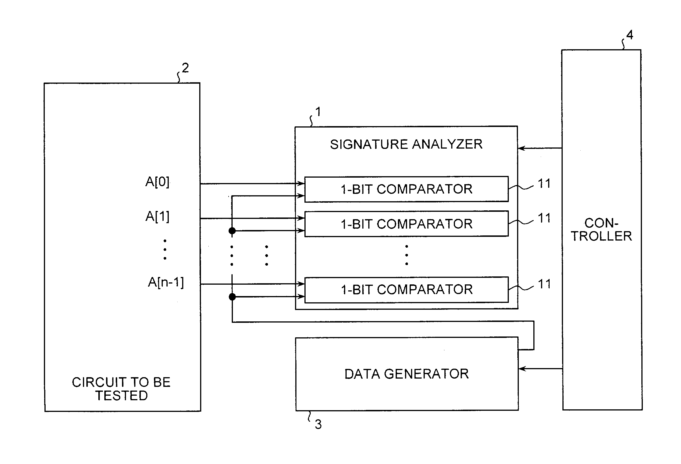
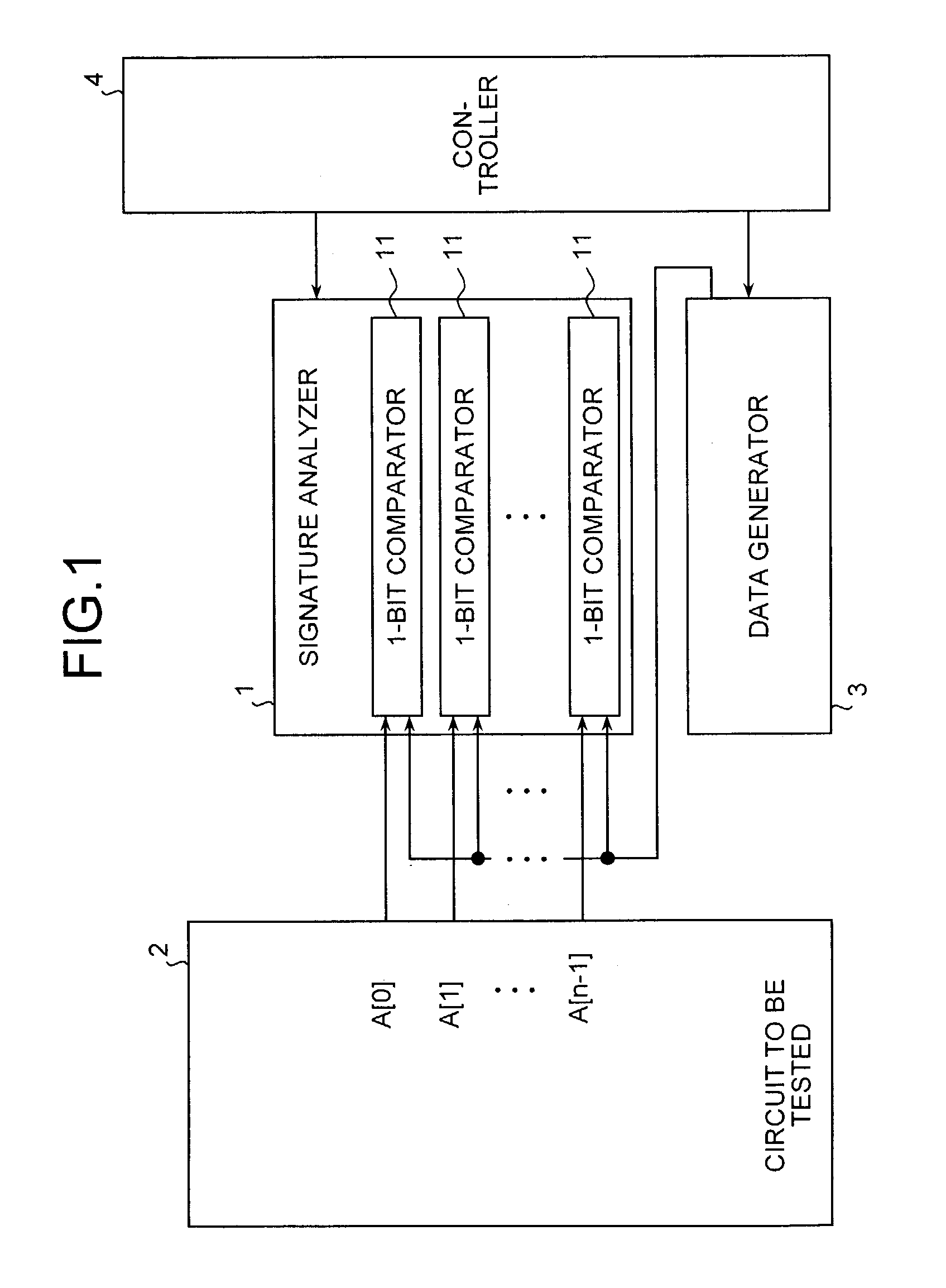
[0035]The signature analyzer 101 has n / 2 1-bit comparators 11. Each of the 1-bit comparators 11 individually corresponds to each of the selectors 61. Therefore, either one of two data output bits in a group corresponding to the data output bits is supplied to each 1-bit comparator 11 via a corresponding selecto...
second embodiment
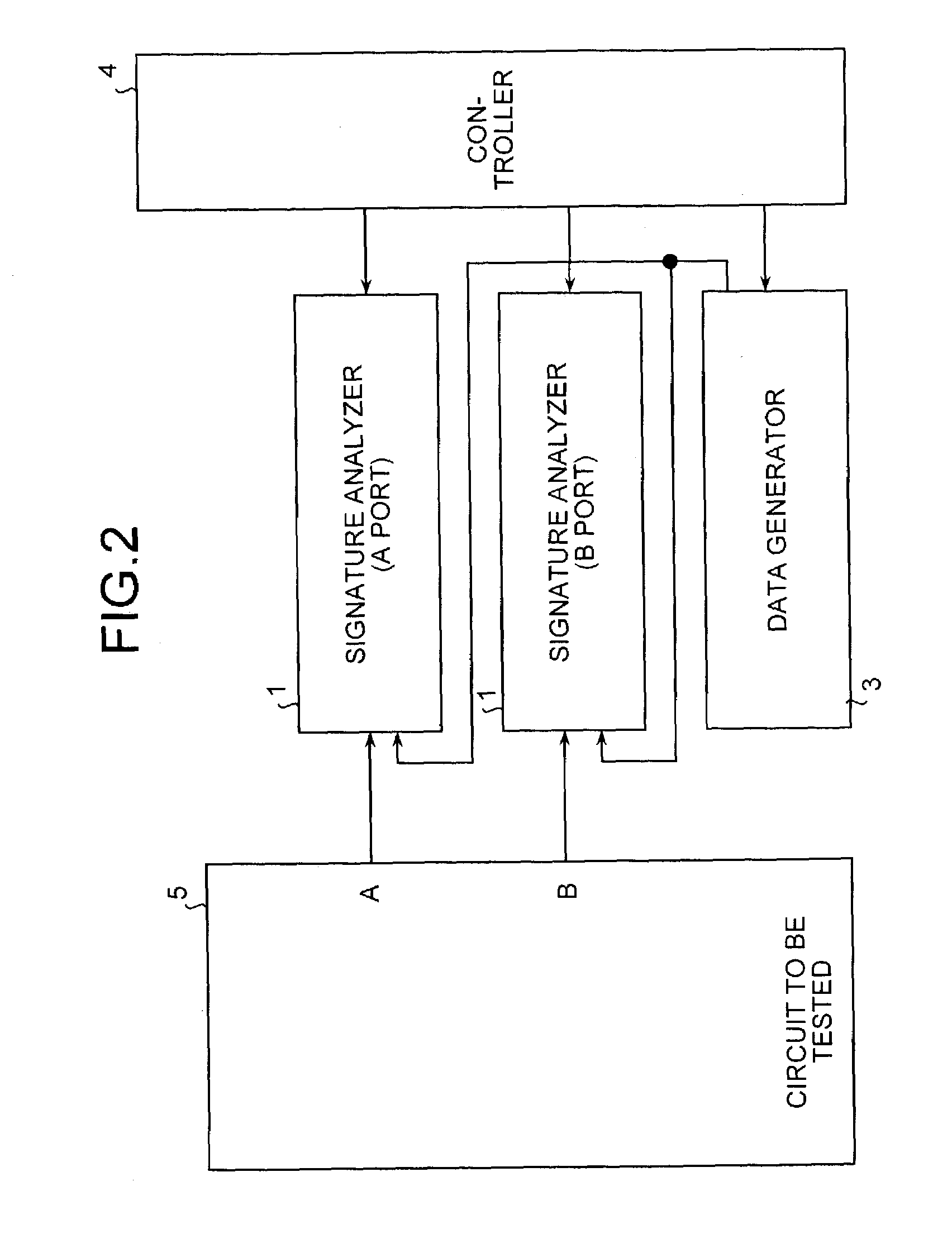
[0050]FIG. 7 shows a block diagram of the configuration of a RAMBIST circuit according to the present invention. As shown in FIG. 7, the RAMBIST circuit comprises a signature analyzer 1, a data generator 3, a controller 204, and a port selector 7 provided with at least one selector. For example, the port selector 7 is provided with one selector 71. The selector 71 selects either the data output from a read port A or the data output from a read port B of the RAM macro 5 as a circuit to be tested.
[0051]The signature analyzer 1 is provided with one bit comparator for one selector 71. The data output from the read port A or the data output from the read port B is supplied to the signature analyzer 1 via the selector 71. The data generator 3 generates expected value data under the control of the controller 204, and supplies the generated expected value data to the signature analyzer 1. The controller 204 controls the signature analyzer 1 to operate, and controls the selector 71 to select...
third embodiment
[0068]FIG. 13 is a flowchart showing one example of a test sequence executed in the RAMBIST circuit according to the When the test is started, for example, the read ports A of the RAM macro 5 are first selected by the port selector 7, and for example, even bits in the port selector 7 are selected by the bit changer 6. The test is then executed on the even bits of the read ports A (step S111). After the test on the even bits is ended, for example, odd bits of the port selector 7 are selected by the bit changer 6 (step S112). The test is then carried out on the odd bits of the read ports A (step S113).
[0069]After the test on the odd bits of the read ports A is ended, for example, the read ports B of the RAM macro 5 are selected by the port selector 7 (step S114). For example, even bits in the port selector 7 are selected by the bit changer 6. The test on the even bits of the read ports B is then carried out (step S115). After the test on the even bits is ended, for example, odd bits ...
PUM
 Abstract
Description
Claims
Application Information
 - R&D
- Intellectual Property
- Life Sciences
- Materials
- Tech Scout
- Unparalleled Data Quality
- Higher Quality Content
- 60% Fewer Hallucinations
Browse by: Latest US Patents, China's latest patents, Technical Efficacy Thesaurus, Application Domain, Technology Topic, Popular Technical Reports.
© 2025 PatSnap. All rights reserved.Legal|Privacy policy|Modern Slavery Act Transparency Statement|Sitemap|About US| Contact US: help@patsnap.com