Jam resistant staple holding track for staplers

a stapler and staple technology, applied in the field of desktop staplers, to achieve the effect of reducing the peak for

Active Publication Date: 2006-10-10
WORKTOOLS
View PDF18 Cites 28 Cited by
  • Summary
  • Abstract
  • Description
  • Claims
  • Application Information

AI Technical Summary

Benefits of technology

[0007]To overcome the strength of a glued bond it is familiar that peeling off portions of the bond until the entire bond is detached is easier than pulling at the entire bond at once. The same approach may be used to reduce the peak force required to shear the front staple of a rack.
[0010]According to the above structure the force required to separate a front staple from a staple rack is greatly reduced. Therefore a low force spring can cause such a separation even when pressing statically. When used in a direct action stapler the reduced separation force will be provide an easier operation.

Problems solved by technology

Therefore a low force spring can cause such a separation even when pressing statically.

Method used


Image

  • Jam resistant staple holding track for staplers
  • Jam resistant staple holding track for staplers
  • Jam resistant staple holding track for staplers

Examples


Embodiment Construction

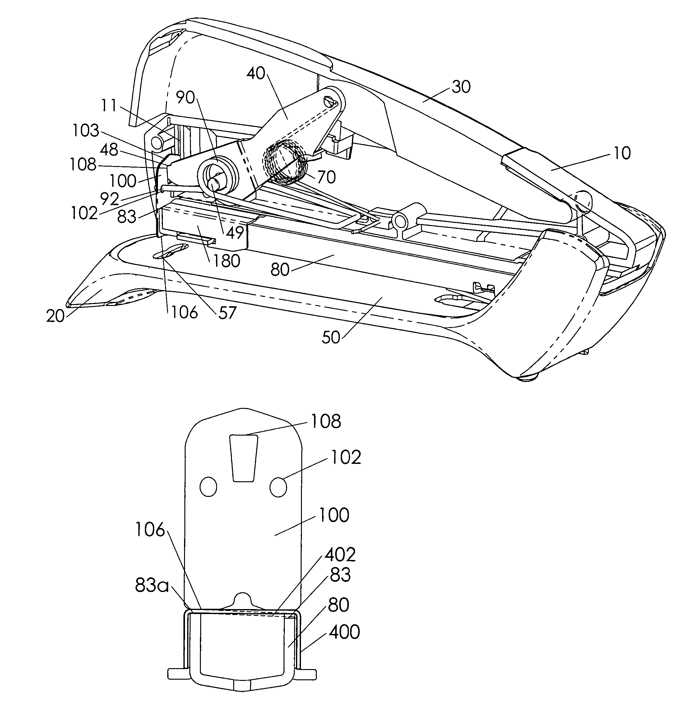
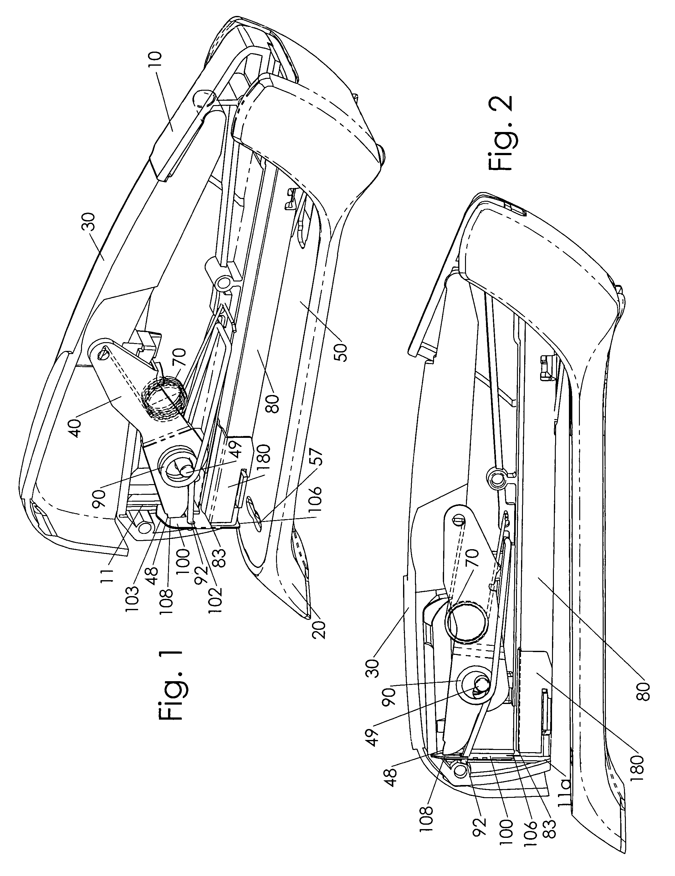
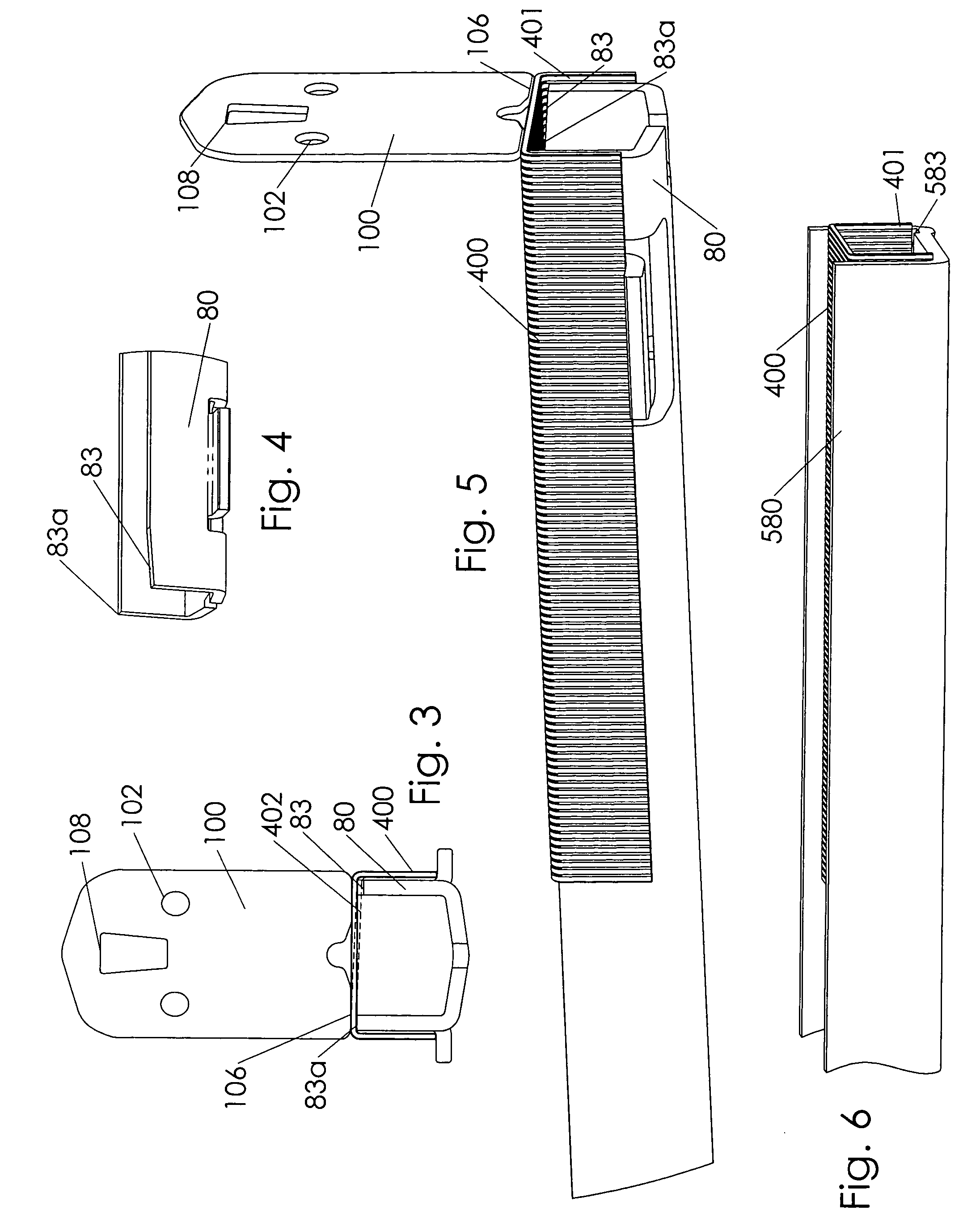
[0019]FIGS. 1 and 2 show a spring actuated desktop stapler as disclosed in co-pending U.S. patent application Ser. No. 10 / 443,854. In FIG. 1 the stapler is in a rest position. Body 10 is shown with the left side removed. Handle 30 pivots about body 10 toward the lower handle position shown in FIG. 2. Body 10 is pivotally mounted to base 20 whereby the front end of body 10 can pivot toward base 20. Cover plate 50 is fitted to base 20 and includes staple forming anvil 57. Lever 40 is linked to handle 30 at a rear lever end and to striker 100 at lever front end 48. Lever front end 48 engages slot 108, FIG. 3, of striker 100. When handle 30 is lowered lever 40 rotates clockwise in FIGS. 1 and 2 so that striker 100 moves upward. At the lever upper position shown in FIG. 2 lever front end 48 is just disengaged from striker slot 108. Striker 100 then instantly moves downward and ejects a staple out by an impact blow. Track 80 includes two parallel rails 88, FIG. 4, that hold and guide stap...


PUM


Abstract

An anti-jamming design for a stapler track provides reduced force to shear a staple from a rack of staples. In stapling, a front staple must be separated from a rack of staples to eject the staple out. Conventional staplers shear the glue that holds the staples together all at once, so the peak force to separate the staple is high. In the present invention the glue that holds staples together in a rack is sheared by a peeling action. Locally progressing sections of glue are peeled as the front staple is sheared from the adjacent second staple. According to one embodiment of the invention progressive shearing is provided by an asymmetric track front end, whereby the front staples are fully supported on one side only so that the staple rack twists as the striker slowly presses down. The striker contacts the supported, higher, side of the staple first and the staple begins to shear from this higher side. When used in a low force spring actuated stapler, the present invention prevents the striker from resting atop the staple in an energized state if the stapling cycle is not properly completed.

Description

FIELD OF THE INVENTION[0001]The present invention relates to desktop staplers. More precisely the present invention discloses improvements to a staple feeding system.BACKGROUND OF THE INVENTION[0002]For consumer applications staples are used in both staple guns and desktop staplers. Both may be referred to as staplers. Staple guns usually employ a heavier staple and stapling mechanism than desktop staplers, and do not include a separate base and anvil element. However desktop staplers may also be of a heavy-duty format if intended for large stacks of paper. Standard light duty staplers typically fasten a maximum of 20 sheets of paper.[0003]The staples are provided in a rack that includes a line of staples glued together edge-to-edge. The strength of the glue must be sufficient to hold the rack together during handling and use of the staples. The staples are held in or on a track; a front most staple extends past the track to a position under a striker. The striker shears off the fro...

Claims


Application Information

Patent Timeline
Patent Type & Authority Patents(United States)
IPC IPC(8): B25C1/06B25C5/02B25C5/16
CPCB25C5/0242B25C5/1665B25C5/1637
Inventor MARKS, JOEL
Owner WORKTOOLS
Why Eureka
Try Eureka