Shaft coupling

a shaft and coupling technology, applied in the direction of couplings, rod connections, manufacturing tools, etc., can solve the problems of limiting the torque that can be transmitted, difficult to provide an adequate clamping force, and difficult to design and dimension, so as to reduce the torque or axial force transmitting capability of the coupling, prevent or counteract fretting, and be easy to design and dimension.

Inactive Publication Date: 2006-10-10
ROLLS ROYCE AB
View PDF9 Cites 9 Cited by
  • Summary
  • Abstract
  • Description
  • Claims
  • Application Information

AI Technical Summary

Benefits of technology

[0019]An important property of the coupling according to the invention is that it can readily be designed and dimensioned such that the positive or interlocking connection of the coupling sleeve with the shaft member or members is in itself adequate to provide the desired torque and axial-force transmission capability of the coupling, so that it will not be necessary to rely also on a frictional engagement, although a frictional engagement can be present to provide additional safety. Accordingly, it is possible, without thereby necessarily reducing the torque or axial-force transmitting capability of the coupling to a dangerous extent, to apply a surface-protective agent on the internal surfaces of the coupling sleeve halves contacting the external shaft member surfaces in order to prevent or counteract fretting of these surfaces and to facilitate mounting and dismounting of the coupling.

Problems solved by technology

In prior art split clamping couplings the retaining device is problematic, however.
One disadvantage is that the keyways form stress concentration areas in the coupling sleeve and in the shaft member or members and therefore limit the torque that can be transmitted.
Another disadvantage is that if the coupling and the shaft member or members have to be positively held together both rotationally and axially to be able to transmit high torques and great axial forces, a retaining device including both at least one axial key and at least one transverse key is required.
A further disadvantage is that it is often difficult to provide an adequate clamping force, that is, adequate friction between the coupling sleeve and the shaft member or members, especially in split clamping couplings which are required to transmit very high torques.
A disadvantage is also that the keyed joints often exhibit a certain rotational play that has undesired effects when the direction of the torque is repeatedly reversed.
Still another problem is that the contact surfaces between the coupling sleeve and the shaft member or members are prone to so-called fretting or chafing corrosion.

Method used


Image

  • Shaft coupling
  • Shaft coupling
  • Shaft coupling

Examples


Embodiment Construction

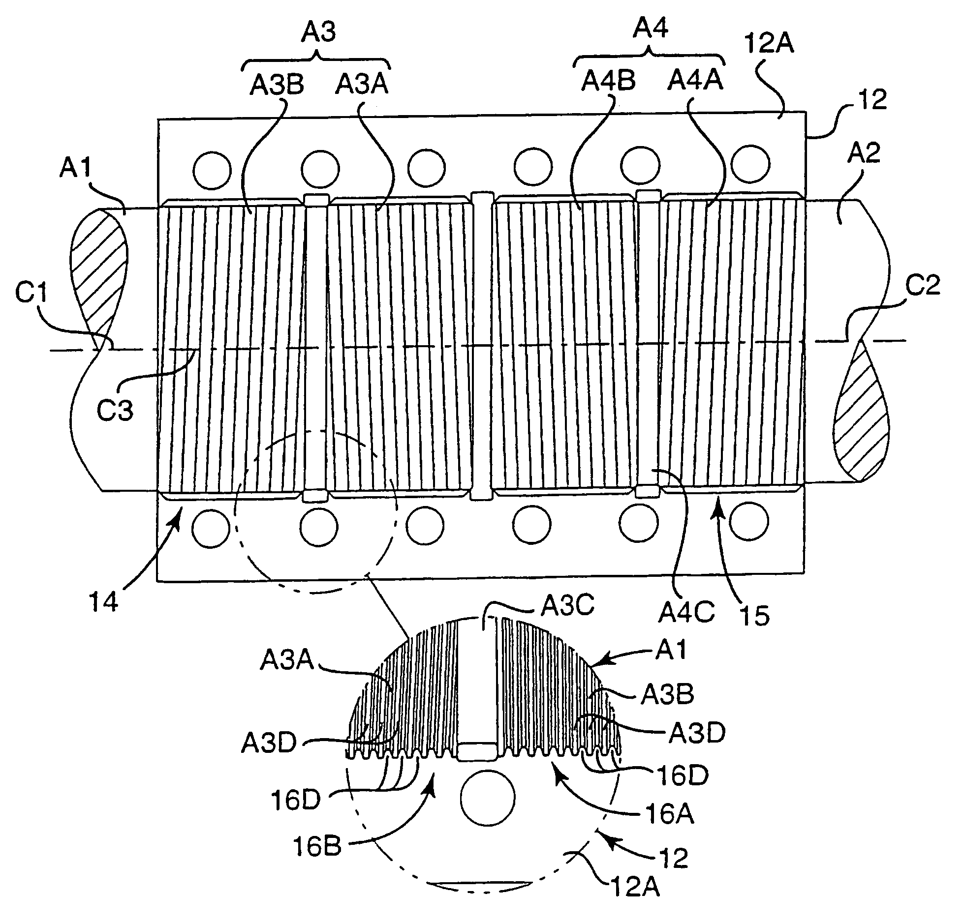
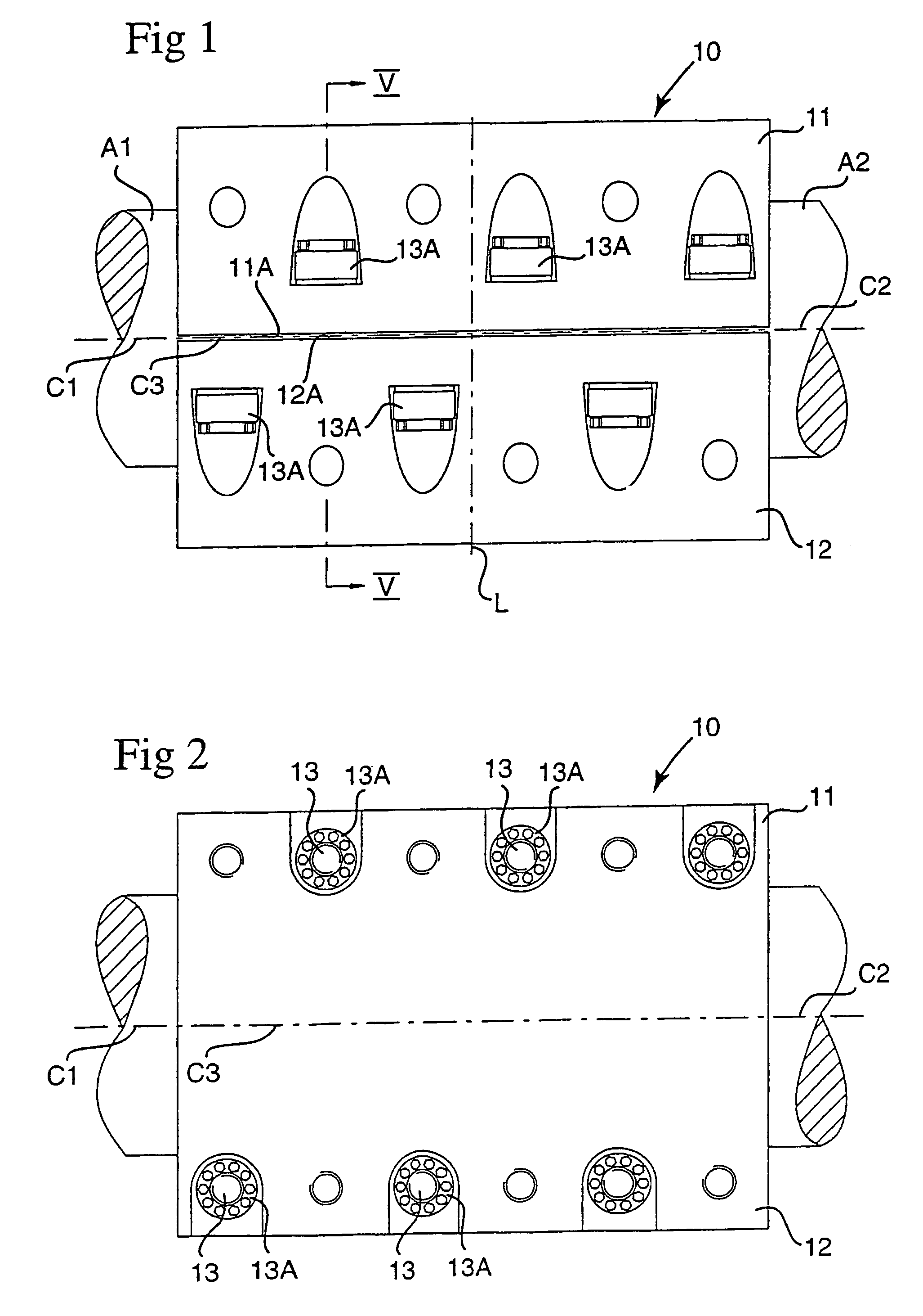
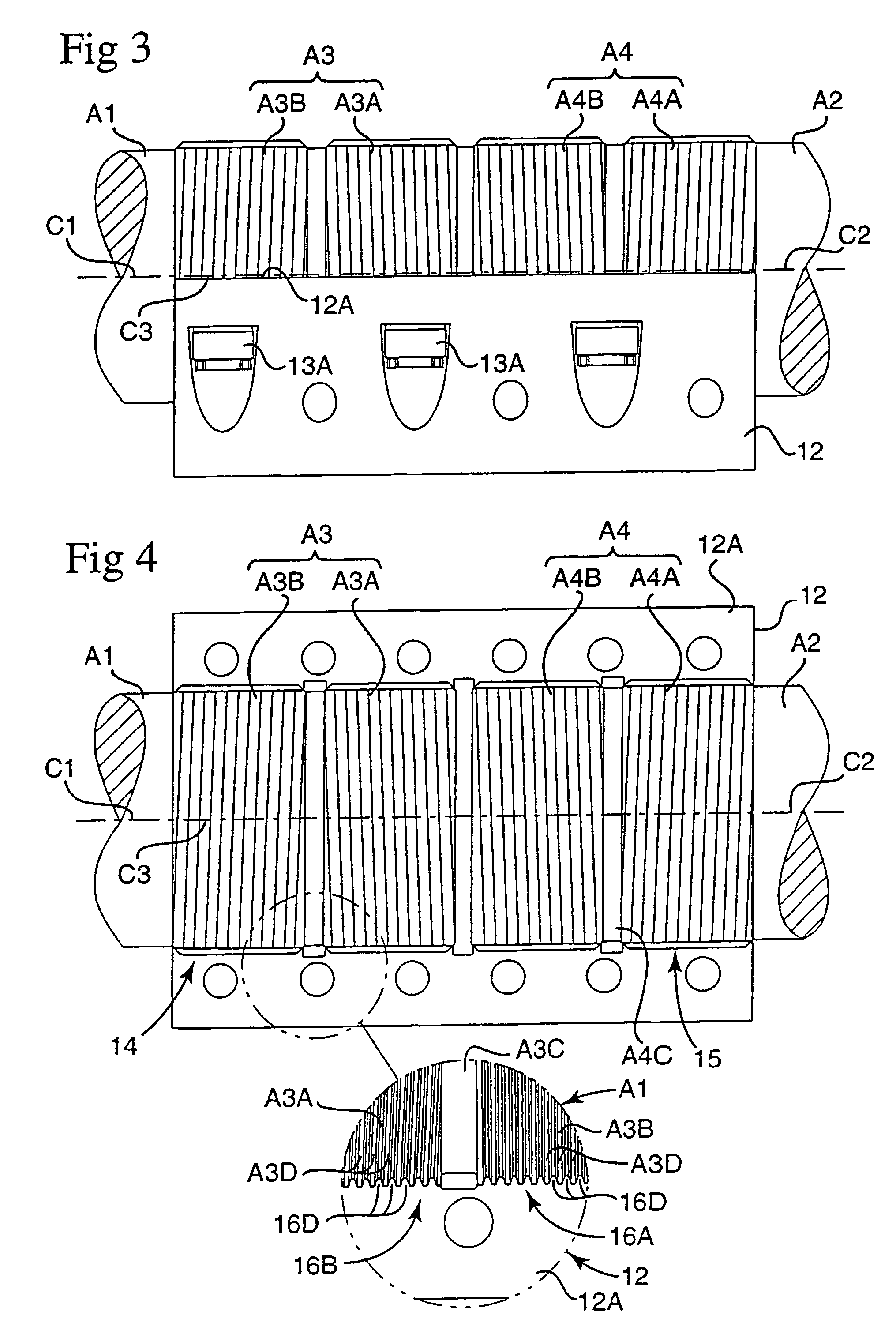
[0029]The shaft coupling shown by way of example in FIGS. 1 to 7 is generally designated by 10. The shaft coupling 10 is intended for holding together two shaft members A1 and A2 which are aligned with their confronting ends close to one another.

[0030]The coupling 10 comprises two substantially identical coupling sleeve halves 11 and 12, which are “diagonal” mirror-image or reverse copies of one another, and a number of clamping elements formed by bolts 13 which hold the coupling sleeve halves together and clamp them about the shaft members A1 and A2 with the axes C1 and C2 of the latter substantially coinciding with the axis C3 of the coupling sleeve.

[0031]When the coupling sleeve halves 11, 12 are clamped together as shown in the drawings, they jointly form a circular cylindrical coupling sleeve which is concentric with and surrounds and firmly interconnects the shaft members A1, A2. As is well known in the art of split clamp couplings, the dimensions of the coupling sleeve halves...


PUM


Abstract

In a shaft coupling having a pair of complementally shaped, detachably joinable coupling sleeve halves (11, 12) which can be clamped together by means of clamping elements to form a split coupling sleeve provided with at least one seat (14) for a first shaft member (A1) which is to be non-rotatably connected with a second shaft member (A2, A2′) so that the first and second shaft members are aligned. The sleeve halves include retaining elements for positively locking the first shaft member (A1) against rotational movement relative to the coupling sleeve, wherein the retaining elements include a plurality of elongate force transmitting elements (16D) in the seat (14, 15)

Description

BACKGROUND OF THE INVENTION[0001]1. Technical Field of the Invention[0002]This invention relates to a shaft coupling comprising a pair of complementally shaped, detachably joinable coupling sleeve halves which form, when they are joined together, a split coupling sleeve having an axis and provided with at least one seat for a first shaft member which is to be non-rotatably connected with a second shaft member so that the first and second shaft members are centred on said axis of the coupling sleeve, clamping elements for holding the coupling sleeve halves together and clamping them about the first shaft member, and a retaining device including interengaging retaining elements for positively locking the first shaft member against rotational movement relative to the coupling sleeve.[0003]2. Prior Art[0004]In known shaft couplings of this kind, also known as split clamping or compression couplings, the retaining device usually comprises a keyed joint having at least one axial key recei...

Claims


Application Information

Patent Timeline
Patent Type & Authority Patents(United States)
IPC IPC(8): F16D1/02F16D1/00F16D1/04
CPCF16D1/04Y10T403/69Y10T403/5786Y10T403/5781Y10T403/556F16D1/0864
Inventor BACSKAY, ISTVAN
Owner ROLLS ROYCE AB
Why Eureka
Try Eureka