Pollen sensor and method

a pollen sensor and sensor technology, applied in the field of pollen sensors and methods, can solve the problems of inability to detect pollen particles on a real time basis, long time-consuming process of above microscope methods, significant drawbacks, etc., and achieve the effect of accurate discrimination of pollen particles, reducing dispersion light volume, and reducing light volum

Inactive Publication Date: 2006-10-10
SHINYEI KAISHA
View PDF5 Cites 19 Cited by
  • Summary
  • Abstract
  • Description
  • Claims
  • Application Information

AI Technical Summary

Benefits of technology

The present invention is a pollen sensor and method that can detect pollen particles in real-time, even when there are other particles present. It is able to accurately identify pollen particles even when the light source is weakening or there is dirt on the lens. This means that the pollen sensor can provide reliable output even when there are multiple particles present.

Problems solved by technology

The technical problem addressed in this patent is the need for a more efficient and accurate method to detect pollen particles in air, without the need for advanced skills or the limitations of current methods such as the microscope method or the use of polarized light.

Method used


Image

  • Pollen sensor and method
  • Pollen sensor and method
  • Pollen sensor and method

Examples


Embodiment Construction

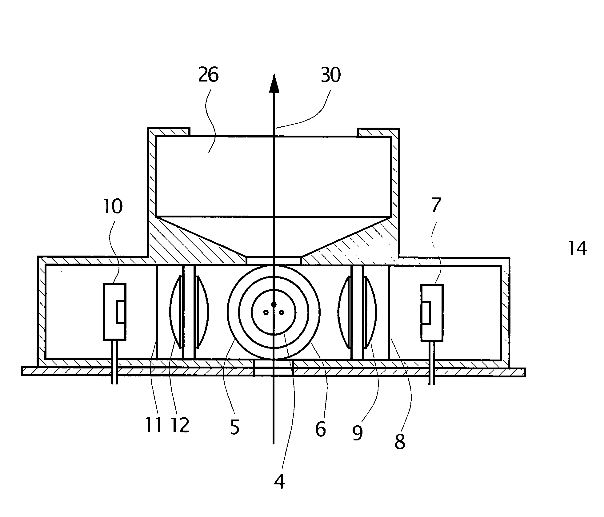
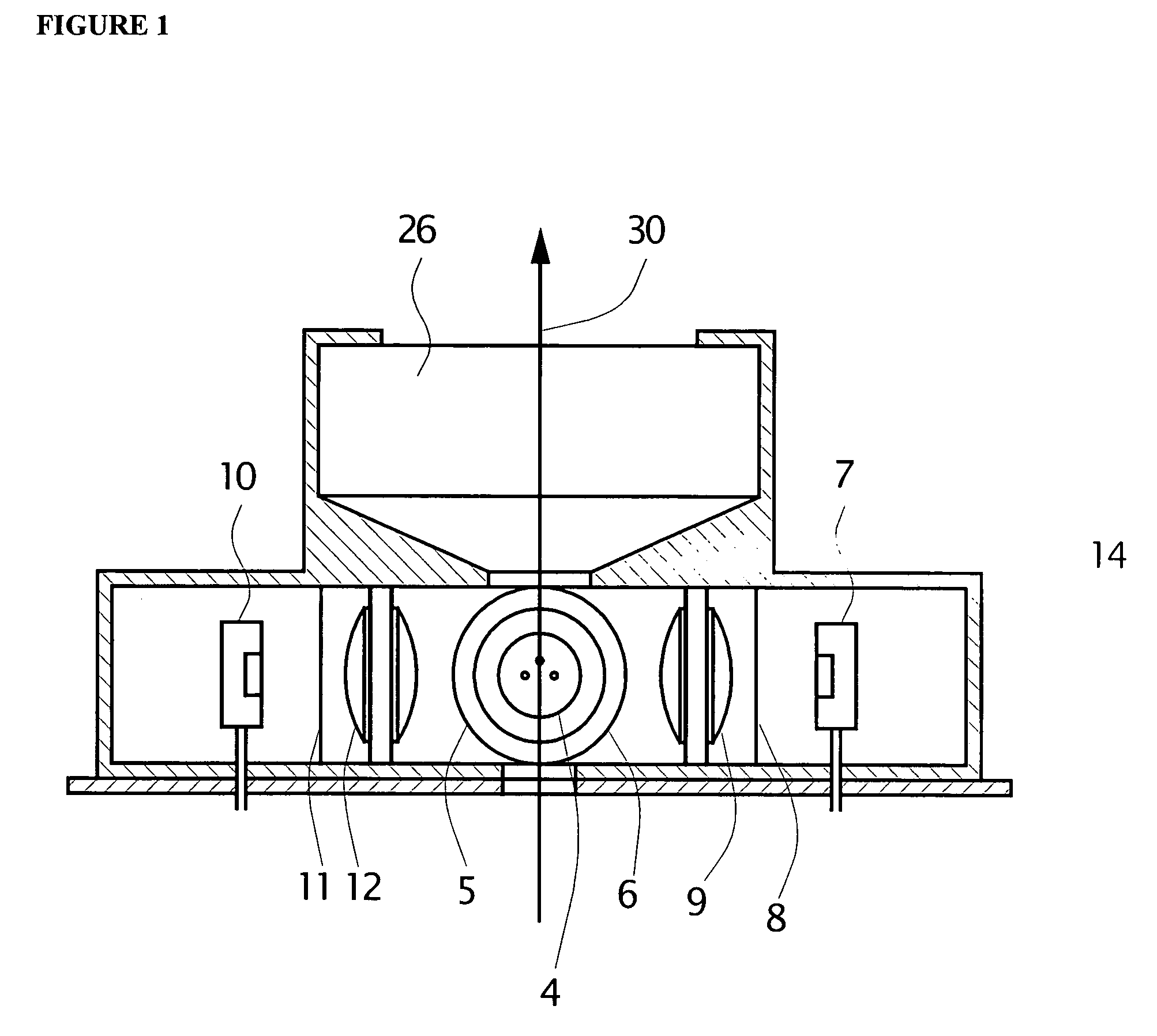
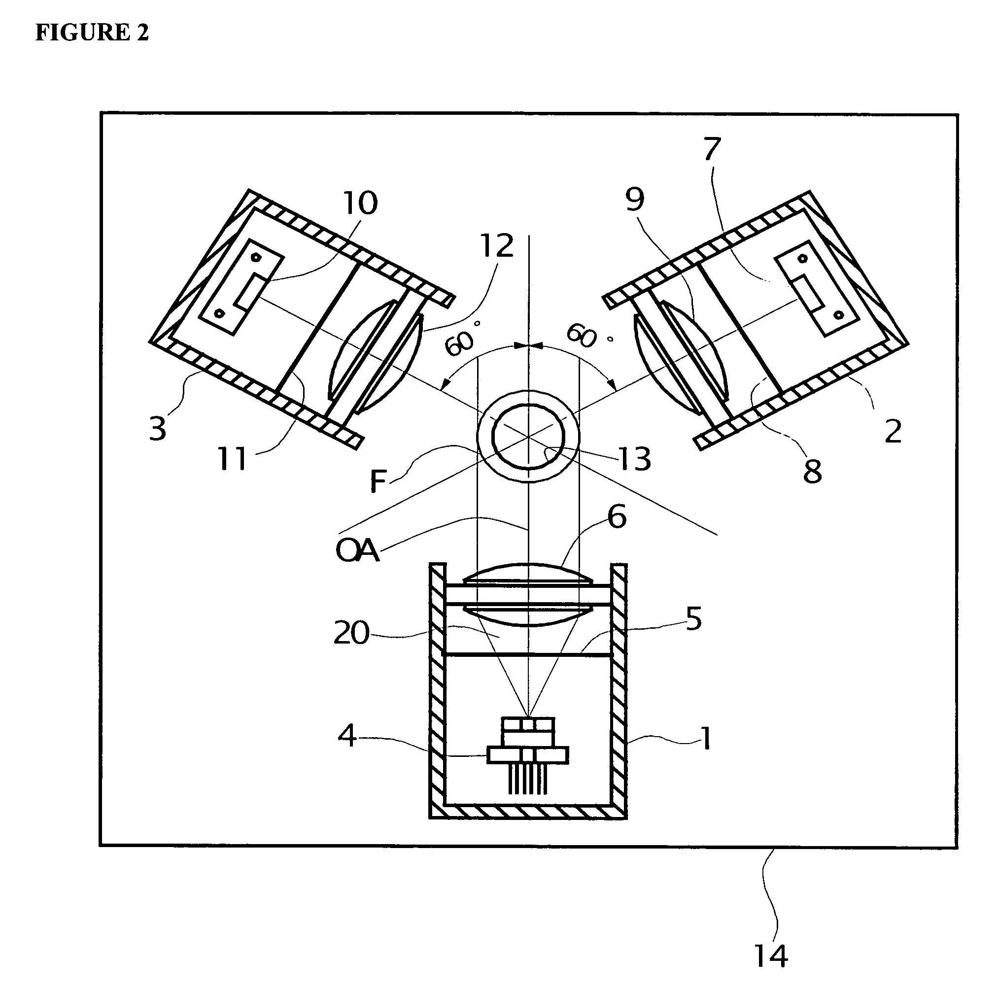
[0023]The present invention is described hereinafter with reference to FIGS. 1–9 of the drawings. As shown in FIGS. 1 and 2, the pollen sensor of the present invention comprises a shielding housing 14 which forms a confined area for housing an illuminating portion 1 containing a light beam generating source 4, preferably a semiconductor laser diode. The light beam generating source generates a light beam 20 for illuminating one or more particles 25 (FIG. 3) floating in air within the detection zone F. The light beam 20 has a direction of polarization 22 perpendicular to the plane of the page of FIG. 2 as is diagrammatically illustrated in FIG. 3. The pollen sensor further comprises a first receiver 2 having a photodiode 7 aligned in the scattering polarizing direction of the light beam 20, preferably at 60 degrees to the incident optical axis “OA” for measuring the intensity (Ip) of light beams polarized in a direction parallel to the incident polarizing direction of light selected ...


PUM


Abstract

A pollen sensor and method for detecting pollen which discriminates pollen particles floating in air from other particles on a real time basis. The pollen sensor includes an illumination position for generating a light beam, a first receiver for measuring the intensity (I) or (Ip) of a light beam scattered by floating particles in a detection zone, a second receiver for measuring the intensity (Is) of a polarized light beam in a direction perpendicular to light illuminated by the light beam and means for measuring the degree of polarization of the particles for distinguishing pollen particles from other particles.

Description


Claims


Application Information

Patent Timeline
Owner SHINYEI KAISHA
Why Eureka
Try Eureka