Connector axial compression tool

a technology for connecting devices and tools, applied in the direction of manufacturing tools, cable junctions, and connection formation by deformation, etc., can solve the problems of increasing installation tooling requirements and labor costs, chuckheads may damage the inner conductor, sealing, or insulator assemblies of the connector interface, and unnecessary labor and costs to repair and replace any damaged components of the electrical connector

Inactive Publication Date: 2006-10-17
ANDREW LLC
View PDF16 Cites 72 Cited by
  • Summary
  • Abstract
  • Description
  • Claims
  • Application Information

AI Technical Summary

Benefits of technology

[0017]The push mechanism 26 may comprise a push bar 38, a push spring 39, a stop 40, a push nut 41, and a key 42. The push mechanism 26 axially slides through the body 10 of the tool and is guided by, for example, a guide sleeve 44. The guide sleeve 44 slidably aligns the push mechanism 26 with the longitudinal axis of the tool. The push spring 39 biases the tool into an open position by pushing against the lever end 14 of the guide sleeve 44. On the cable end 12 of the push mechanism 26, the key 42 is inserted into a push aperture 46 formed in the cradle 18 and is fastened in place, for example, via the cradle support nut 36 and the cradle washer 37. The key 42 helps to prevent any rotational movements of the cradle 18 with respect to the push mechanism 26.
[0023]From the foregoing, one skilled in the art will appreciate that the invention provides a single cost effective tool to axially compress connectors having any of a wide range of different connector interfaces 64 to cables 51 without damaging the connector interface 64 and or the inner workings of each connector.

Problems solved by technology

Maintaining a range of different connector interface specific tools and or exchanging the chuckheads as different connector interfaces are encountered, increases installation tooling requirements and labor costs.
If there is any axial misalignment during the compression, the chuckheads may damage the inner conductor, sealing, and or insulator assemblies of the connector interface.
This also may result in unnecessary labor and costs to repair and or replace any damaged components of the electrical connector and electrical cable assembly.
Competition within the electrical connector industry has focused attention on equipment and tooling costs, as well as time requirements for installation of electrical connectors.

Method used


Image

  • Connector axial compression tool
  • Connector axial compression tool
  • Connector axial compression tool

Examples


Embodiment Construction

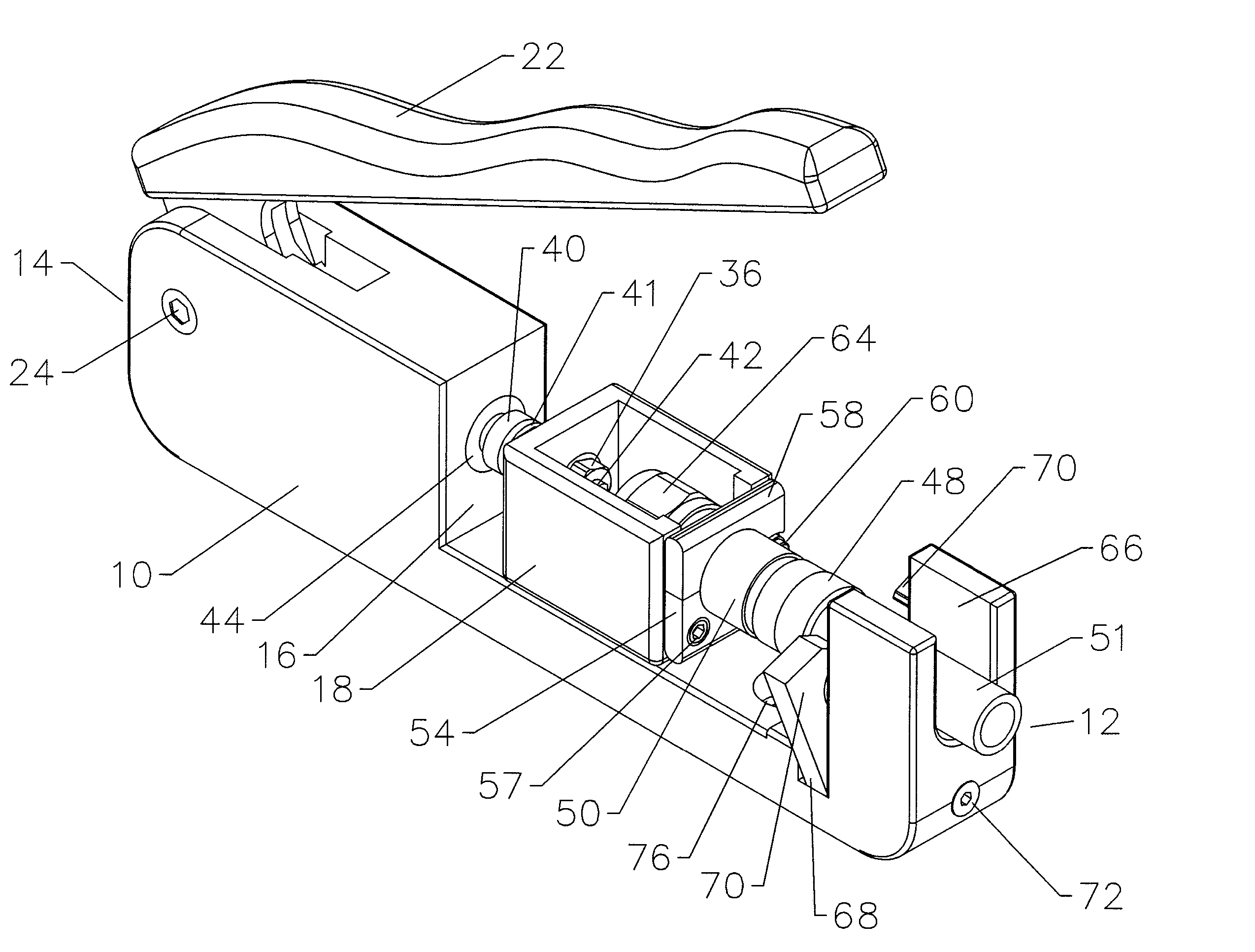
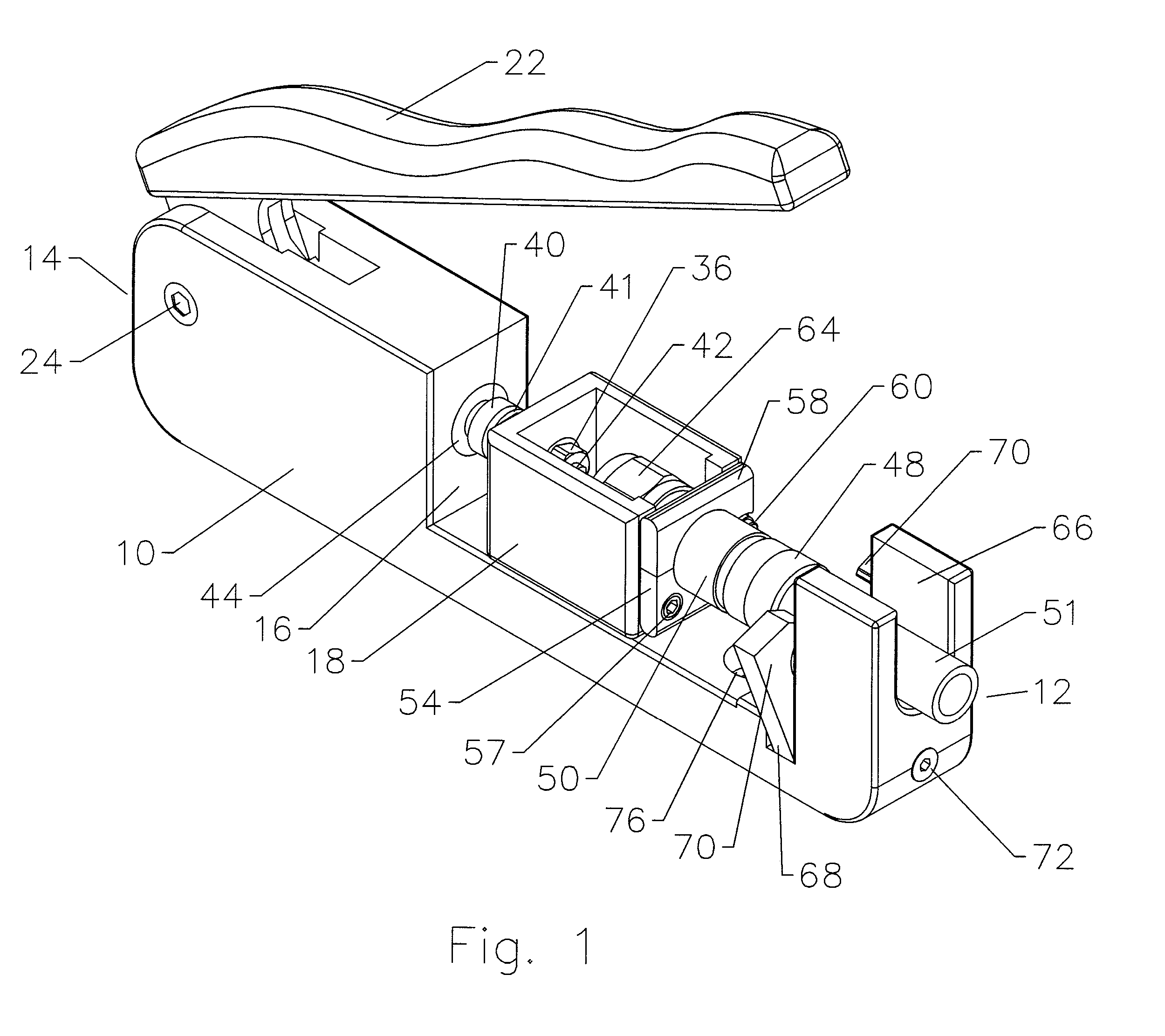
[0015]For purposes of illustration, exemplary embodiment(s) of the present invention are shown in FIGS. 1–5. As shown in FIG. 1, a body 10 comprises a cable end 12 and a lever end 14. On the body 10 and towards the cable end 12 there is an open cavity 16 adapted to receive an axially movable cradle 18.

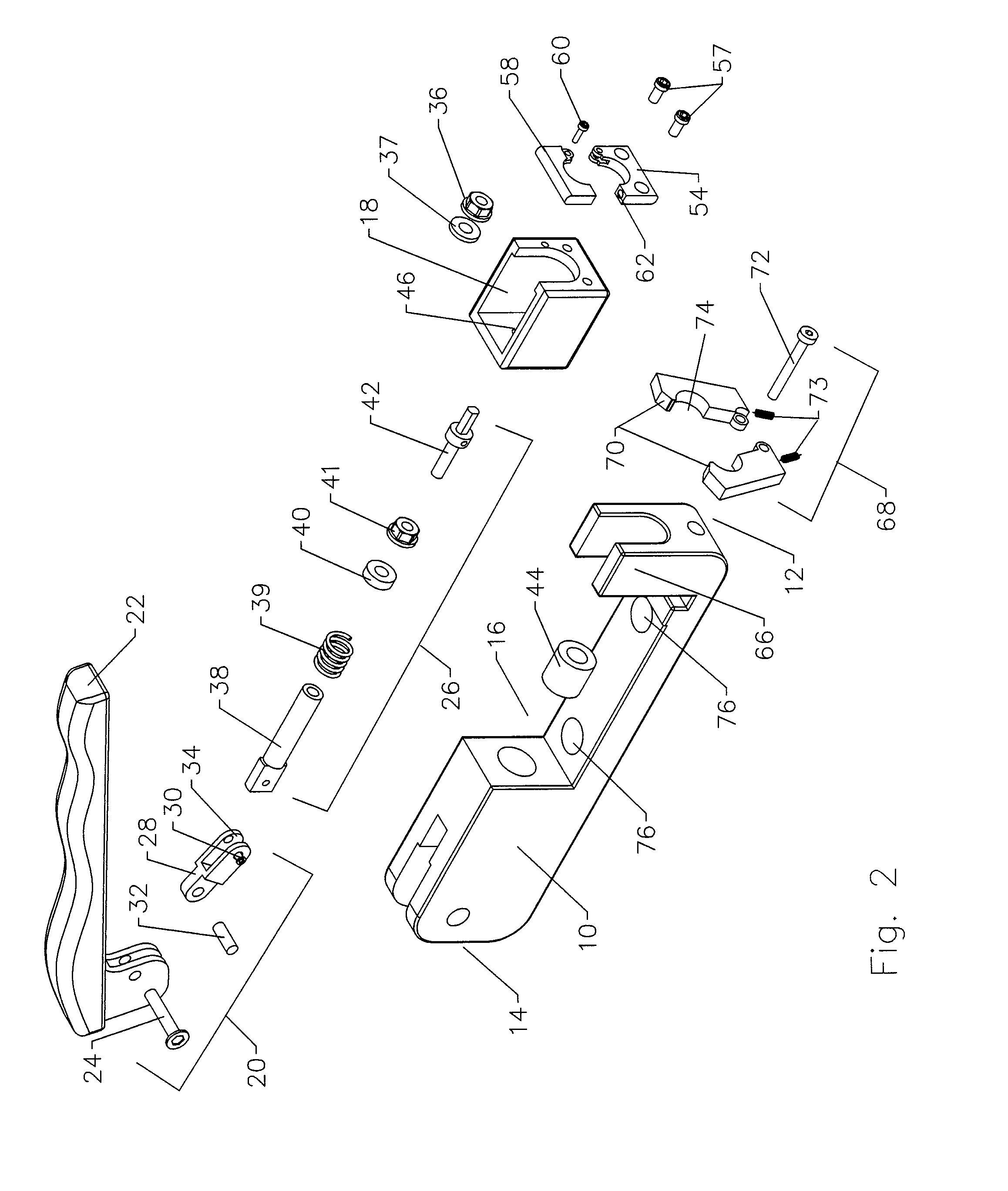
[0016]The movement of the cradle 18 is managed by its connection to a lever mechanism 20 as shown, for example in FIG. 2. The lever mechanism 20 links a handle 22 to the body 10 via a handle axle 24. Pivotal movements of the handle 22 about the handle axle 24 actuate axial movements of the cradle 18 via, for example, a push shank 28 coupled at a lever end 14 to an offset area of the handle 22 by a support axle 32. A push axle 30 links the push shank 28 to the lever end 14 of the push mechanism 26. The cable end 12 of the push shank 28 may have, for example, a forked arm 34 to receive the push mechanism 26. The cable end 12 of the push mechanism 26 may be coupled to the cradle 18, for e...


PUM

PropertyMeasurementUnit
inner diameteraaaaaaaaaa
diameteraaaaaaaaaa
compression forceaaaaaaaaaa

Abstract

A connector axial compression tool having a lever end and a cable end, with a body slidably supporting a cradle in a cavity formed in the body. The cradle is slidable via a handle which pivots about the body, linked to the cradle by a lever mechanism. The cradle has a shoulder clamp adapted to mate with a connector body. Operation of the handle moves the cradle towards and away from a cable end of the cavity, against a cable clamp through which the cable may pass but against which a cable clamp sleeve of the connector abuts, axially compressing the connector to couple it to the cable. Because the shoulder clamp holds the connector body rather than pressing against the connector interface, a wide range of different connectors may be used with the same tool, without causing damage to the connector interface of the various connectors.

Description

BACKGROUND OF INVENTION[0001]1. Field of the Invention[0002]This invention relates to a tool for installation of electrical connectors upon an electrical cable. More particularly, the invention is concerned with an axial compression tool, which accepts electrical connectors having a range of different connector interfaces.[0003]2. Description of Related Art[0004]There have been advancements in connectors adapted for installation by compression fit. U.S. patent application Ser. No. 10 / 708,278 “Axial Compression Electrical Connector” filed Feb. 20, 2003 by Islam et al, assigned to Andrew Corporation of Orland Park, Ill., as is the present invention, describes several embodiments of such connectors. Electrical connectors adapted for installation upon electrical cables by axial compression are field installable using an axial compression hand tool. The prior axial compression tools typically comprise a lever action, which actuates a chuckhead towards the connector interface of the elect...

Claims


Application Information

Patent Timeline
Patent Type & Authority Patents(United States)
IPC IPC(8): B23P19/00
CPCB25B27/10H01R43/0425H01R9/0518Y10T29/53222Y10T29/49181Y10T29/53226Y10T29/53213Y10T29/5327Y10T29/53257Y10T29/49218H02G15/08
Inventor ISLAM, NAHIDLEE, JOONBALL, DAVID JOHNBURKE, RODGER
Owner ANDREW LLC
Why Eureka
Try Eureka