
Method of fabricating security door

a technology of security doors and manufacturing methods, applied in the field of security doors, can solve the problems that the operation of spot welding machines requires no particular skill, and achieve the effects of avoiding the need for skill and/or expense, strength and rigidity, and structural strength and rigidity

Inactive Publication Date: 2006-10-17
COLUMBIA MFG
View PDF18 Cites 19 Cited by
  • Summary
  • Abstract
  • Description
  • Claims
  • Application Information

AI Technical Summary

Benefits of technology

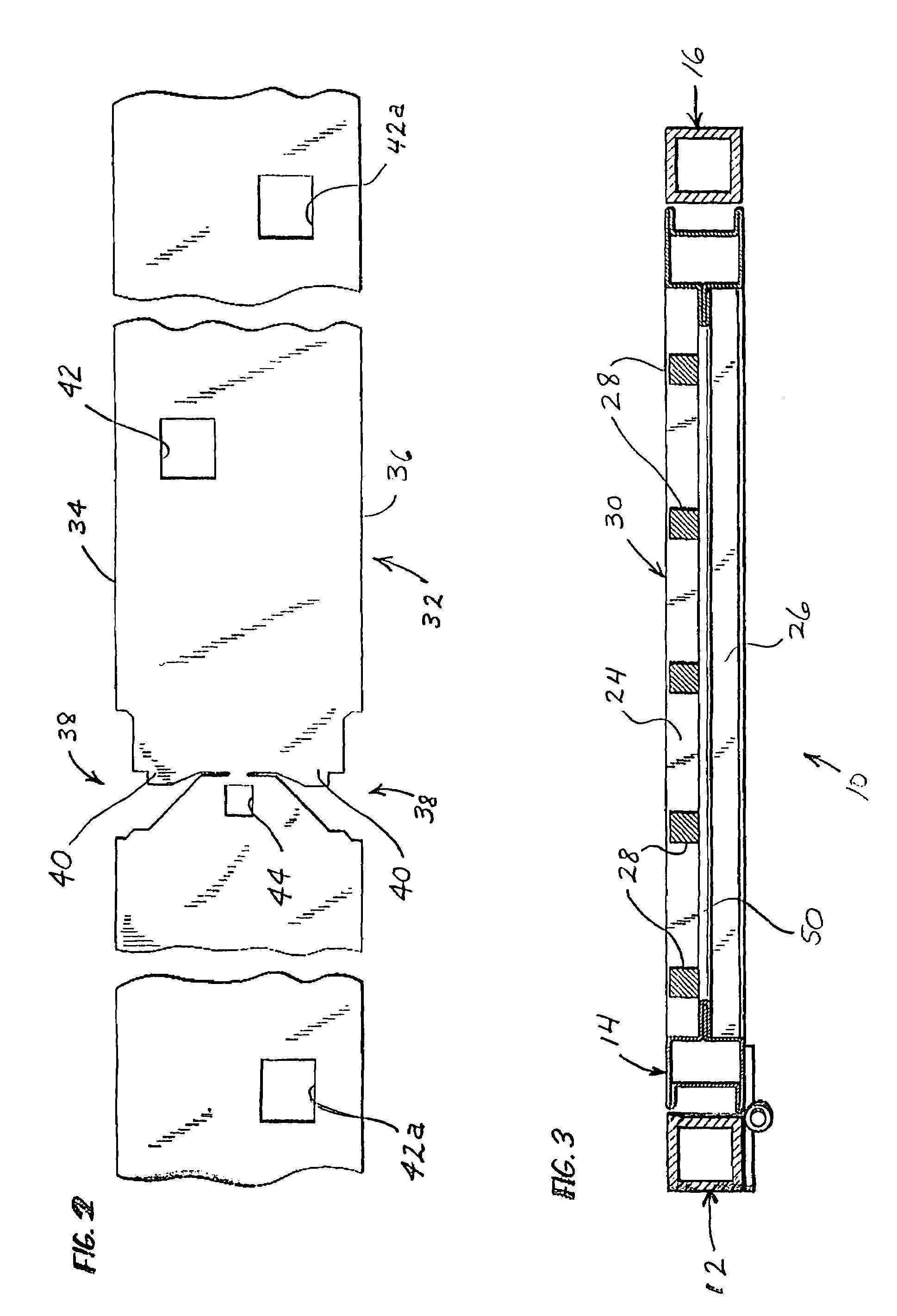
[0008]A primary object of the present invention is to provide a system for fabricating security doors which avoids the need for the skill and / or expense involved in attaching security bars into a surrounding frame of a security door by arc welding, but which produces a security door having the strength and rigidity previously obtained only through the use of arc welding. According to the present invention the structural strength and rigidity necessary for a security door is achieved by forming the metal frame of the door with hollow segments in which security bar receiving apertures have been defined, and attaching the bars of the security door to the surrounding frame with spot welds. The structure of the door is such that portions of the frame reside in a face-to-face disposition with surfaces of the bars. Such a face-to-face relationship between metal surfaces is necessary in order for the process of spot welding to be effective.
[0011]By utilizing a spot welding process according to the present invention in the fabrication of a security door, it is possible to from the stiles and rails of the door frame from sheet metal using a roll-forming process. This allows a thinner gage of steel to be used in the construction of the stiles and rails, but the door frame is even stronger than conventional security door frames because stiffening ribs or flanges can be roll-formed into the sheet metal. As a consequence, even thought the frame members forming the door frame of the present invention are lighter in weight than conventional door frame members of the same size, the door frame members of the present invention have a stronger bending moment than their conventional counterparts.
[0012]It would not be possible to fasten the bars of a security door to roll-formed sheet metal stile and rail members using conventional methods of security door fabrication, since any attempt to arc weld the bars to the sheet metal frame members would cause holes to be burnt through the sheet metal stock of the frame members. However, by utilizing the technique of spot welding rather than arc welding it is possible to secure security bars to roll-formed sheet metal stile and rail members to form a security door that is lighter in weight, stronger, and cheaper to manufacture than conventional security doors.
[0017]The pairs of corner securing tabs can either be formed as longitudinal extensions from both ends of the upper and lower rail members, longitudinal extensions from both ends of the stile members, or longitudinal extensions from one end of each of the members. The corner securing tabs are arranged in pairs so as to stiffen both the interior and exterior faces of the door frame.

Problems solved by technology

Nevertheless, operation of a spot welding machine requires no particular skill.

Method used


Image

  • Method of fabricating security door
  • Method of fabricating security door
  • Method of fabricating security door

Examples


Embodiment Construction

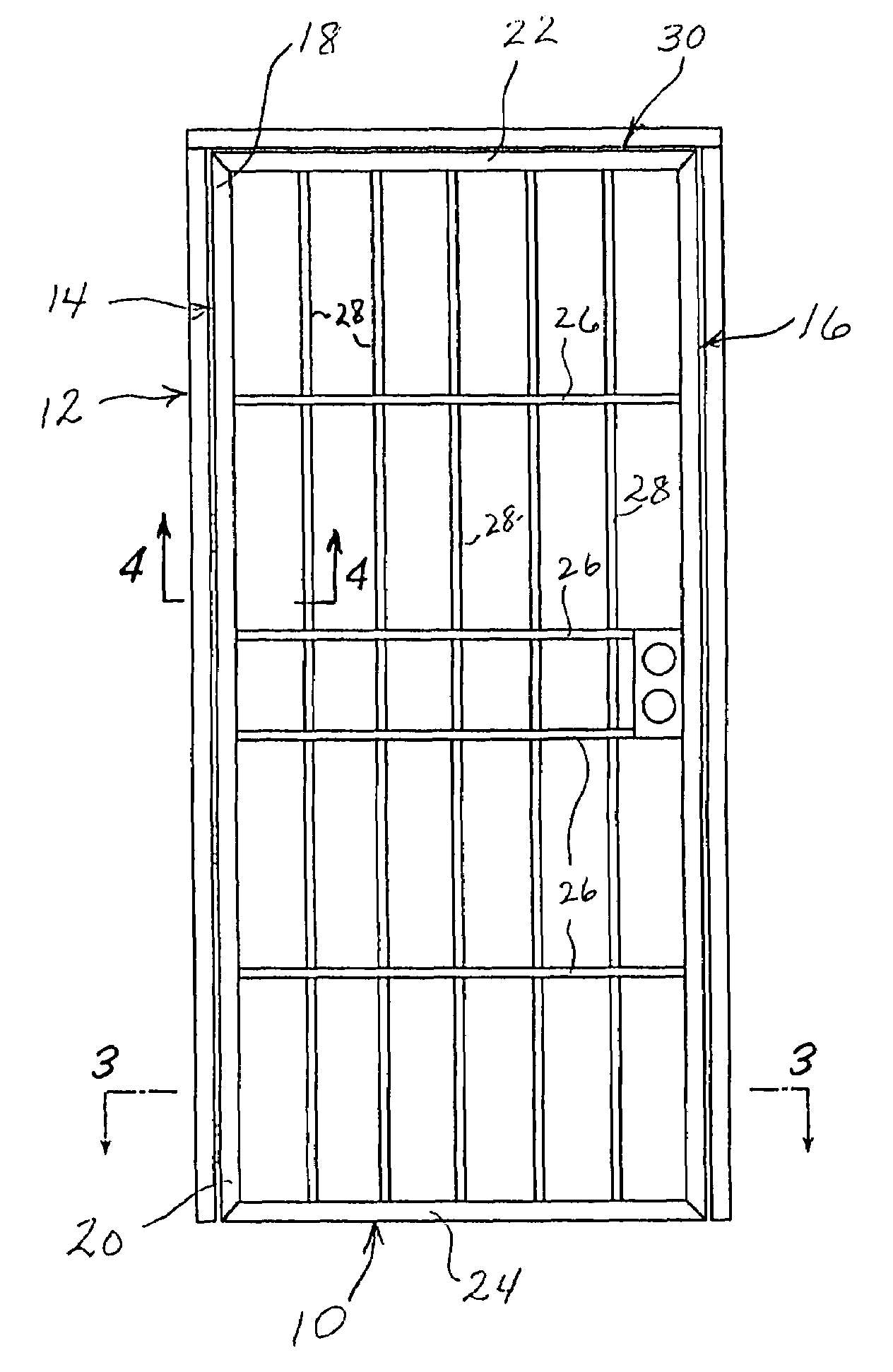
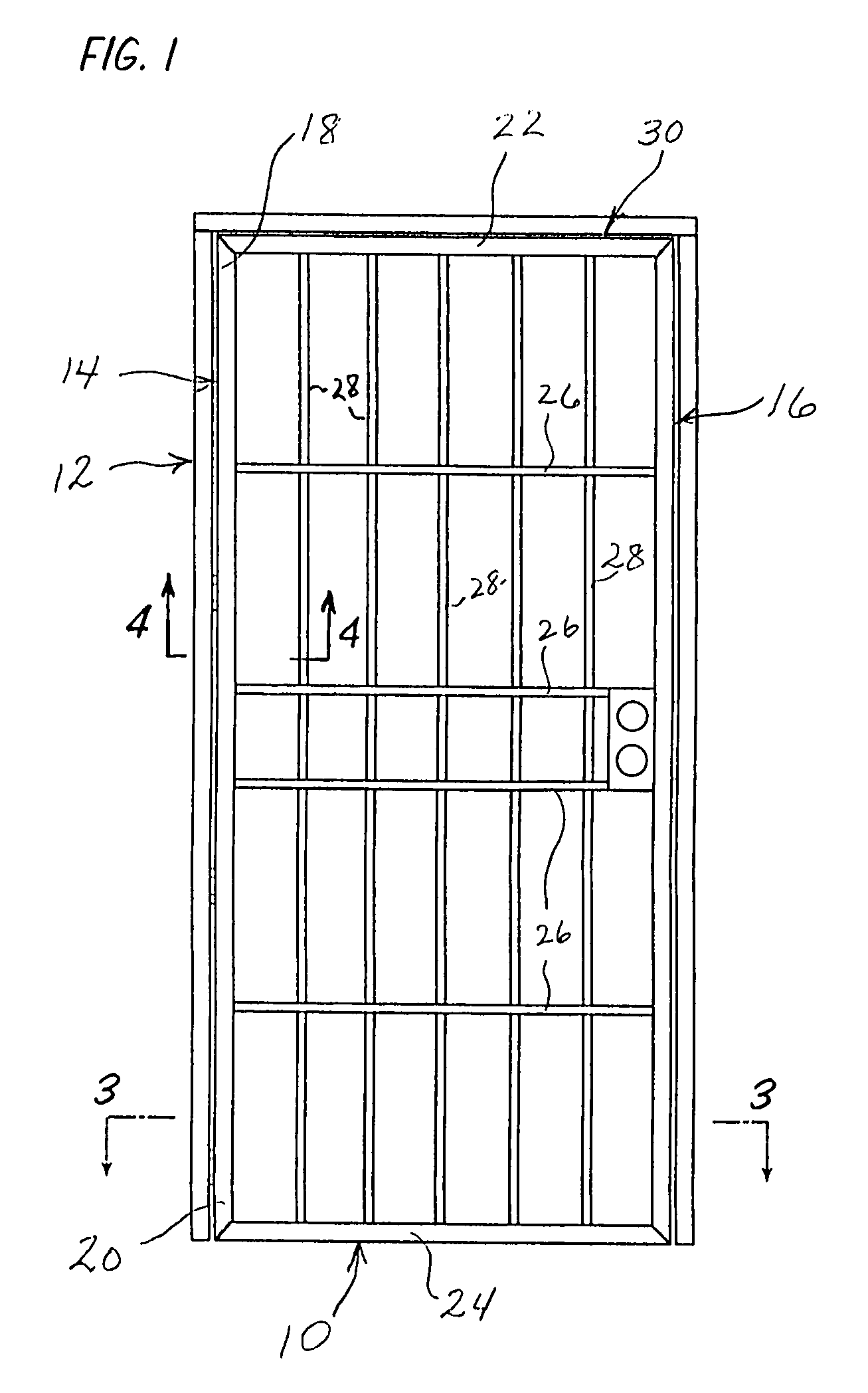
[0029]FIG. 1 illustrates a security door 10 fabricated according to the invention and mounted within a frame 12 in the manner in which the security door 10 is installed in a door opening in a building. The security door 10 is comprised of a mutually parallel pair of hollow, roll-formed sheet metal upright stiles 14 and 16 each having opposing extremities 18 and 20. The security door 10 also is formed with a hollow, roll-formed sheet metal upper transverse rail 22 and a corresponding lower transverse rail 24 of the same construction. The upper and lower rails 22 and 24 are collected to the extremities 18 and 20 of the upright stiles 14 and 16 and are oriented perpendicular thereto. Together the stiles 14 and 16 and the upper and lower rails 22 and 24 form a metal door perimeter frame 30. Steel security bars 26 one-half inch square extend between and are spot welded to the upright stiles 14 and 16. Other steel security bars 28 also one-half inch square extend between and are spot weld...


PUM

PropertyMeasurementUnit
thicknessaaaaaaaaaa
thicknessaaaaaaaaaa
perimeteraaaaaaaaaa

Abstract

A security door for a gate or building opening is formed of a metal frame that defines a pair of hollow stile frame members and upper and lower hollow transverse rail frame members. Each of the frame members has an inner face with an attachment flange projecting therefrom. Security receiving apertures are defined in the inner faces of the frame members. In the fabrication of the door a plurality of metal security bars are positioned relative to the hollow frame member so that the ends of the security bars project through the security bar receiving apertures and into the hollow frame members. The security bars pass over and reside in contact with the attachment flanges. The security bars are spot welded to the attachment flanges so as to permanently secure them to the door frame. Also, the frame itself is preferably formed from a single, elongated strip of metal that is roll formed and then bent at mitered corner cuts to create and delineate the stile and rail members. Corner fastening tabs are preferably formed on at least some of these members so as to reside in contact with the ends of other of the frame members located immediately adjacent thereto. The fastening tabs are secured by spot welding to the adjacent members which they contact.

Description

[0001]The present application is a division of U.S. patent application Ser. No. 08 / 976,763 filed Nov. 24, 1997, now U.S. Pat. No. 5,979,137.BACKGROUND OF THE INVENTION[0002]1. Field of the Invention[0003]The present invention relates to a security door and a method of manufacturing a security door.[0004]2. Description of the Prior Art[0005]With the rise of anxiety concerning both personal safety and the security of property, the use of security doors has become increasingly commonplace. Conventional security doors are formed of rectangular frames of heavy metal tubing, often drawn and rolled steel having a thickness of about 0.090 inches. The steel tubing is formed to create upright stile members and upper and lower transverse rail members extending between the stile members. To create security, a grid of metal bars is provided across the rectangular opening defined between the stile and rail members. Some of these metal bars extend parallel to the stiles and are anchored to the tra...

Claims


Application Information

Patent Timeline
Patent Type & Authority Patents(United States)
IPC IPC(8): B23P15/00E06B9/04
CPCE06B9/04Y10T29/49837Y10T29/49966Y10T29/49829Y10T29/49627
Inventor SHOUP, CURTIS C.
Owner COLUMBIA MFG
Learn More