Snow removal machine

a technology of snow removal machine and blower, which is applied in the direction of snow cleaning, way cleaning, construction, etc., can solve the problems of preventing the blower from providing a sufficient torque to efficiently, unfavorable for reducing the weight of the blower, and unfavorable for reducing the size of the engine, so as to avoid the power loss of the engine and increase the strength of the blower

Active Publication Date: 2006-10-17
HONDA MOTOR CO LTD
View PDF11 Cites 21 Cited by
  • Summary
  • Abstract
  • Description
  • Claims
  • Application Information

AI Technical Summary

Benefits of technology

[0020]Each supporting member in the present invention preferably has an opening for allowing snow left on the supporting member to fall therethrough after the throwing-up blade throws up snow. Snow left on the supporting members is let fall through the openings to prevent remaini

Problems solved by technology

The remaining snow on the supporting members adds its weight to the blower, preventing the blower from providing a sufficient torque to efficiently throw up snow to the chute.
Further, for an extra load to the blower, it is required to increase the strength of the blower t

Method used


Image

  • Snow removal machine
  • Snow removal machine
  • Snow removal machine

Examples


first embodiment

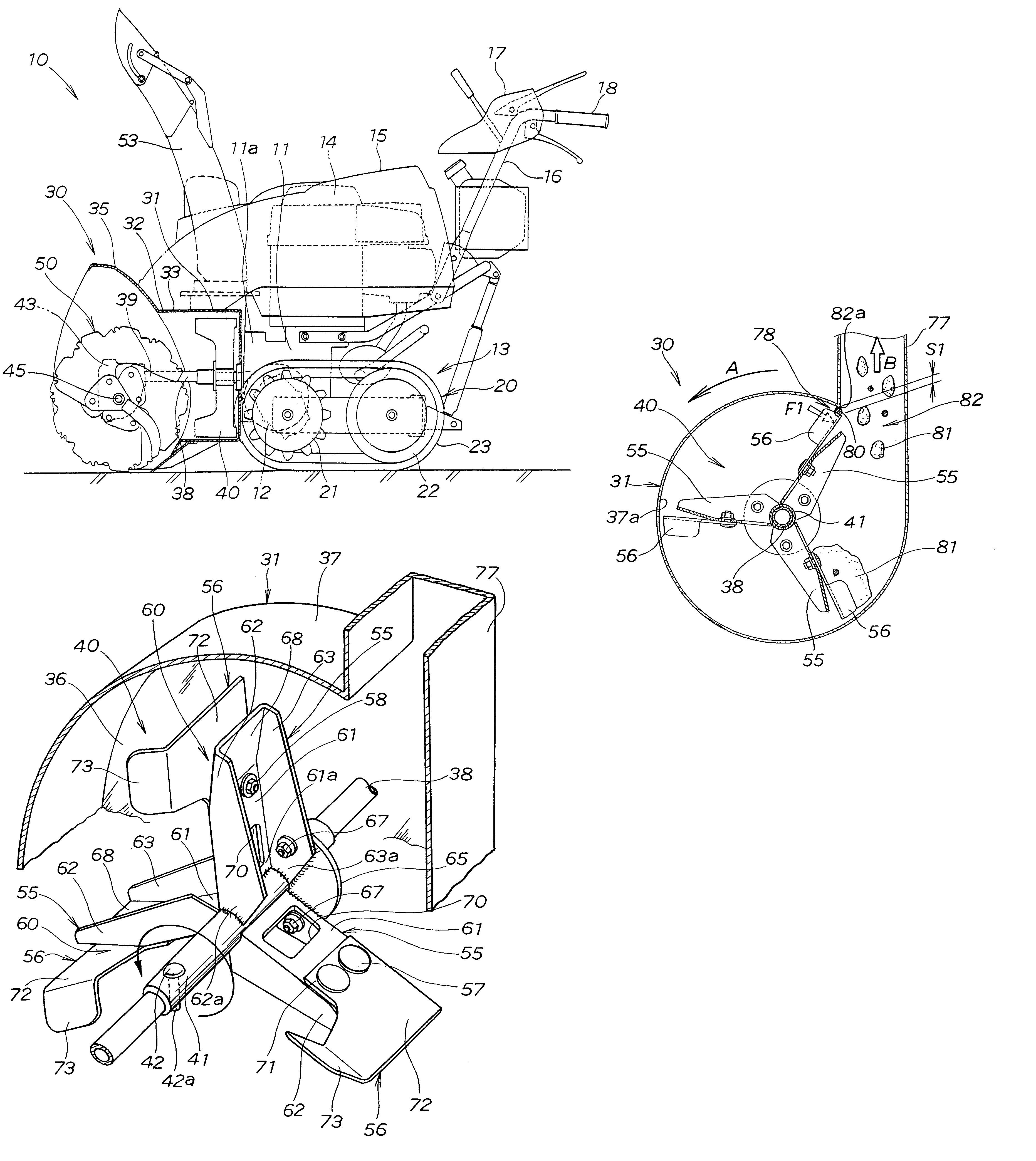
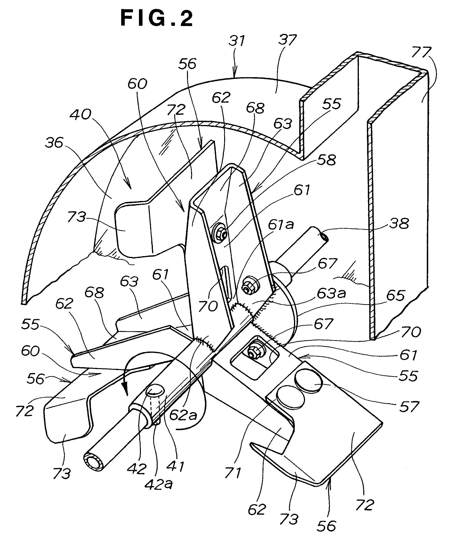
[0043]FIG. 2 illustrates in a perspective view the blower 40 as a component of the auger unit 30 according to the present invention.

[0044]The blower 40 includes a tube 41 longitudinally fitted onto the drive shaft 38. The tube 41 is coupled to the drive shaft 38 by a coupling pin 42 inserted therethrough. A cotter pin (not shown) for preventing dislocation is inserted into a lower end portion 42a of the coupling pin 42 penetrating through the tube 41 and the drive shaft 38 and protruding from the tube 41, for preventing dislocation of the coupling pin 42. On the tube 41, a plurality of supporting members 55 (three in the embodiment shown in the figure) are radially provided at 120° intervals. Each of the supporting members 55 has an elastically deformable throwing-up blade 56 detachably attached thereto with bolts 57, 57 and nuts 58, 58 (see also FIG. 4). A vacant space 60 is formed between the throwing-up blade 56 and the supporting member 55 to allow the throwing-up blade 56 to be...

second embodiment

[0094]Now, the operation of the blower 90 will be described with reference to FIGS. 8A to 8E.

[0095]Referring to FIG. 8A, the drive shaft 38 is rotated by the engine 14 (see FIG. 1) to rotate left and right augers 50 (see FIG. 1) and the blower 90 as shown by arrow G via the drive shaft 38.

[0096]The left and right augers 50 are rotated to collect snow 81 to the center in the transverse direction. The snow removal machine 10 (see FIG. 1) is moved forward to bring the collected snow 81 into the blower housing 31.

[0097]The snow 81 brought into the blower housing 31 is picked up by each of the throwing-up blades 56 of the blower 90. The picked-up snow 81 is carried on the throwing-up blade 56. The throwing-up blade 56 carrying the snow 81 is then moved to a position below an opening 82 of the blower housing 31.

[0098]Referring to FIG. 8B, when passing from the position below the opening 82 of the blower housing 31 through the opening 82, the throwing-up blade 56 carrying the snow 81 thro...


PUM


Abstract

A snow removal machine of this invention has a blower provided in a blower housing for throwing up snow collected by an auger toward a chute. The blower has a plurality of supporting members provided on a drive shaft for rotating the auger and the blower and a plurality of throwing-up blades attached to the respective supporting members. The throwing-up blades are elastically deformable. A vacant space is formed between the supporting members and the throwing-up blades. The vacant space allows deformation of the throwing-up blades in a direction opposite to the rotation direction of the blower.

Description

FIELD OF THE INVENTION[0001]The present invention relates to a snow removal machine and, more particularly, to an improvement in a blower for throwing up snow collected by an auger toward a chute for throwing the snow through the chute onto a desired location.BACKGROUND OF THE INVENTION[0002]Snow removal machines with an auger unit including a blower for removing snow accumulated on a road surface or the like include a known snow removal machine disclosed, for example, in Japanese Patent Laid-Open Publication No. HEI-3-137311. The auger unit of this snow removal machine including the blower will be described with reference to FIG. 10.[0003]In the auger unit 200 shown in FIG. 10, rotation of a drive shaft 201 causes an auger (not shown) to rotate and also causes a blower 202 to rotate as shown by arrow “a.” Rotation of the auger causes snow to be collected to the center in the transverse direction. Advancement of the auger unit 200 causes the collected snow to be brought into a blowe...

Claims


Application Information

Patent Timeline
IPC IPC(8): E01H5/09E01H5/04
CPCE01H5/045
Inventor SAKAI, SEISHU
Owner HONDA MOTOR CO LTD
Why Eureka
Try Eureka