Ink jet recording apparatus and cleaning control method for recording head incorporated therein

a recording apparatus and cleaning control technology, applied in printing and other directions, can solve the problems of increasing the size of recording equipment, and increasing the cost of recording equipment, and achieve the effect of preventing the breakage of the ink storage section

Inactive Publication Date: 2006-10-17
SEIKO EPSON CORP
View PDF32 Cites 33 Cited by
  • Summary
  • Abstract
  • Description
  • Claims
  • Application Information

AI Technical Summary

Benefits of technology

[0060]The valve unit is opened with the negative pressure accumulated, whereby it is made possible to efficiently discharge the air bubbles entering the recording head, for example, when the ink cartridge is replaced, together with a fast ink flow.
[0193]Owing to the configuration, breakage of the ink storage section can be prevented, ink drips from the recording head or inflow of air from the recording head can also be prevented.

Problems solved by technology

Since ink pressurized in a pressure generating chamber is jetted to recording paper as ink drops from a nozzle for printing, the recording head involves a problem of causing a print failure because of a rise in the ink viscosity and hardening of ink caused by vaporization of a solvent from nozzle orifices, for example, adhesion of dust, mixing of air bubbles, etc.
Thus, if the nozzle orifice is clogged or the ink cartridge is replaced, the nozzle formation face of the recording head is sealed by capping unit and ink is sucked and discharged from the nozzle orifice by negative pressure from a suction pump, whereby clogging caused by ink hardening in the nozzle orifice, etc., and an ink jet failure caused by mixing air bubbles into an ink flow passage are dissolved.
To do this, the pump must be upsized and a large-sized motor for driving the pump must also be used; it is inevitable to increase the costs and upsize the whole recording apparatus.
While a sufficient deaeration degree in the ink cartridge is provided, minute air bubbles in the ink flow passage also dissolve in ink; consequently, the probability that a print failure will be caused by dot dropouts caused by air bubbles is low.
However, if the deaeration degree of ink in the ink cartridge lowers, the capability of dissolving minute air bubbles also lowers, so that the effect of air bubbles is received and a problem of a print failure, etc., occurs.
That is, if a foreign substance of dust, etc., is mixed, a particularly narrow ink supply port in the ink flow passage of the recording head or a nozzle orifice portion is clogged with the foreign substance, so that the normal ink jetting action cannot be executed and it is made impossible to recover the recording head function in many cases.
If such a state is entered, the air bubble in the recording head produces so called cushion action of absorbing pressure change occurring in a pressure chamber based on print data, causing a problem in which it becomes impossible to jet ink from the recording head.
In this case, a part of the air bubble passes through the filter member 407d and can stay in the ink flow passage in the recording head, also causing a problem in which it becomes impossible to jet ink from the recording head, as described above.

Method used


Image

  • Ink jet recording apparatus and cleaning control method for recording head incorporated therein
  • Ink jet recording apparatus and cleaning control method for recording head incorporated therein
  • Ink jet recording apparatus and cleaning control method for recording head incorporated therein

Examples


first embodiment

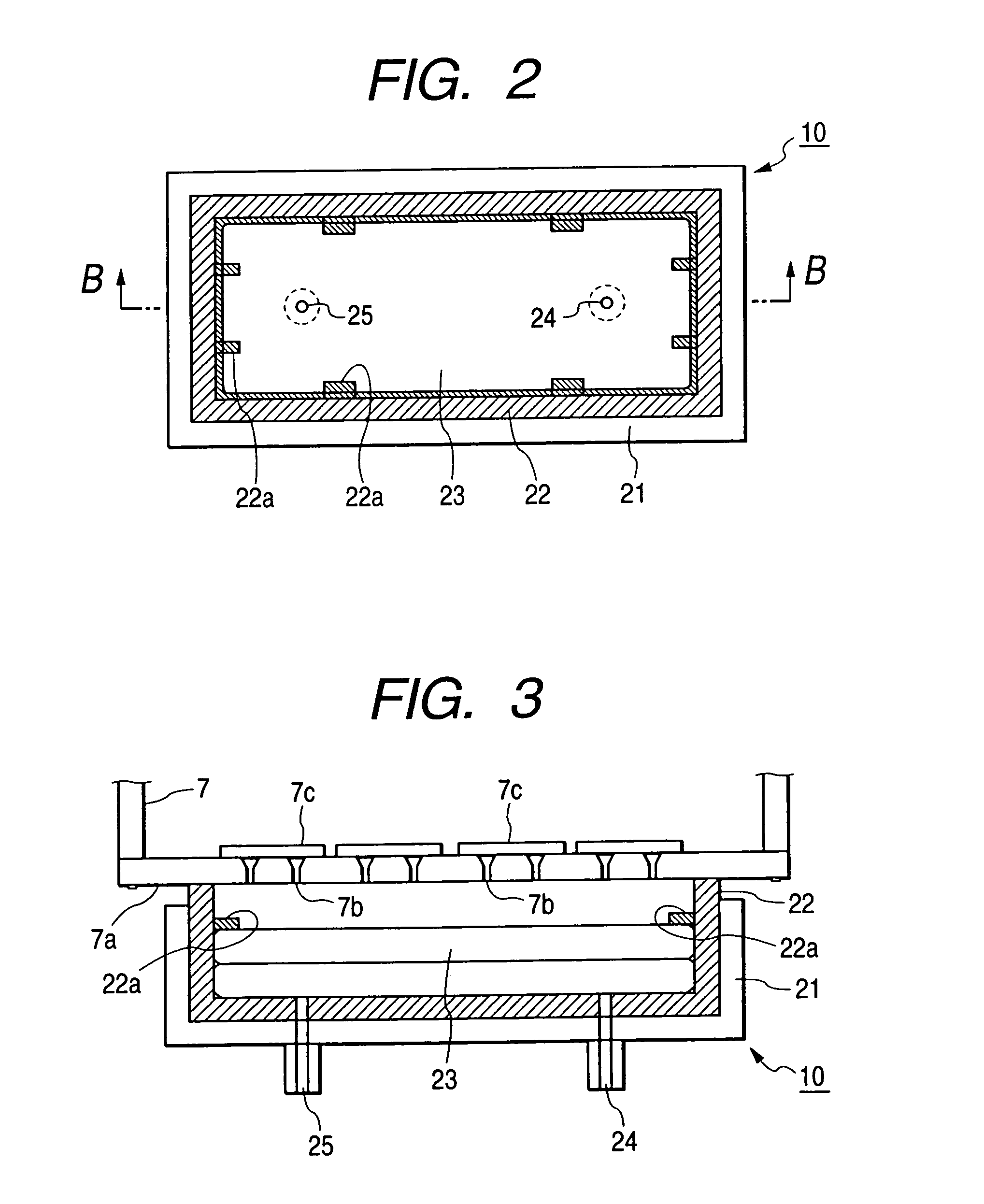
[0299]FIG. 7 shows the state of the negative pressure in the internal space of the capping unit 10 at steps S16 to S19 in the invention.

[0300]That is, in the first embodiment of the invention, the negative pressure in the internal space of the capping unit 10 rises following the track like a quadratic curve at the same time as driving the pump is started, as shown in FIG. 7.

[0301]When the negative pressure reaches the maximum, driving the suction pump is stopped and in this state, a wait is made for expiration of the predetermined time.

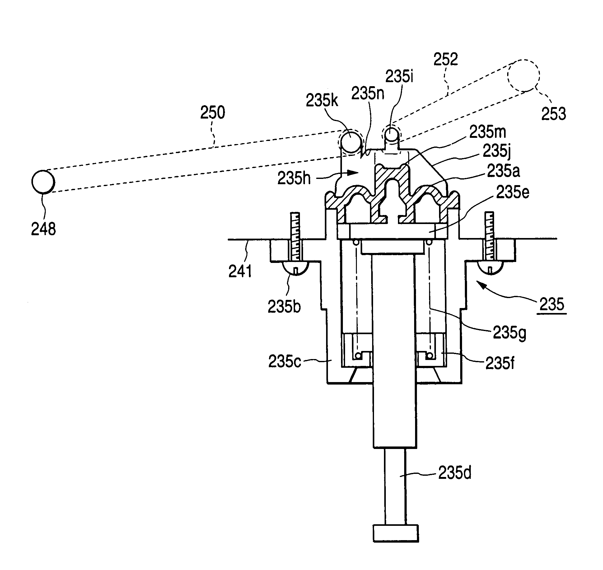
[0302]During the expiration of the predetermined time, the negative pressure acts on the inside of the ink flow passage 35 from the nozzle orifices of the recording head 7 to the valve unit 36. Therefore, the deaeration degree of ink existing in the ink flow passage 35 from the nozzle orifices to the valve unit 36 rises because of the negative pressure and minute bubbles generated accordingly are accumulated as air bubbles and grow with other air bubb...

second embodiment

[0317]Next, an ink jet recording apparatus and a recording head cleaning control method in the recording apparatus in the invention will be discussed.

[0318]FIG. 8 is a flowchart to show the recording head cleaning operation in a second embodiment of the invention, executed in the configuration of the recording apparatus previously described. The cleaning operation sequence in the second embodiment will be discussed with reference to FIG. 8.

[0319]For example, if a cleaning command is received on utilities in the host computer, a control signal is sent from the host computer to the cleaning sequence controller 45 gas shown in FIG. 5, and the cleaning sequence controller 45 outputs various control signals, whereby the cleaning operation is started.

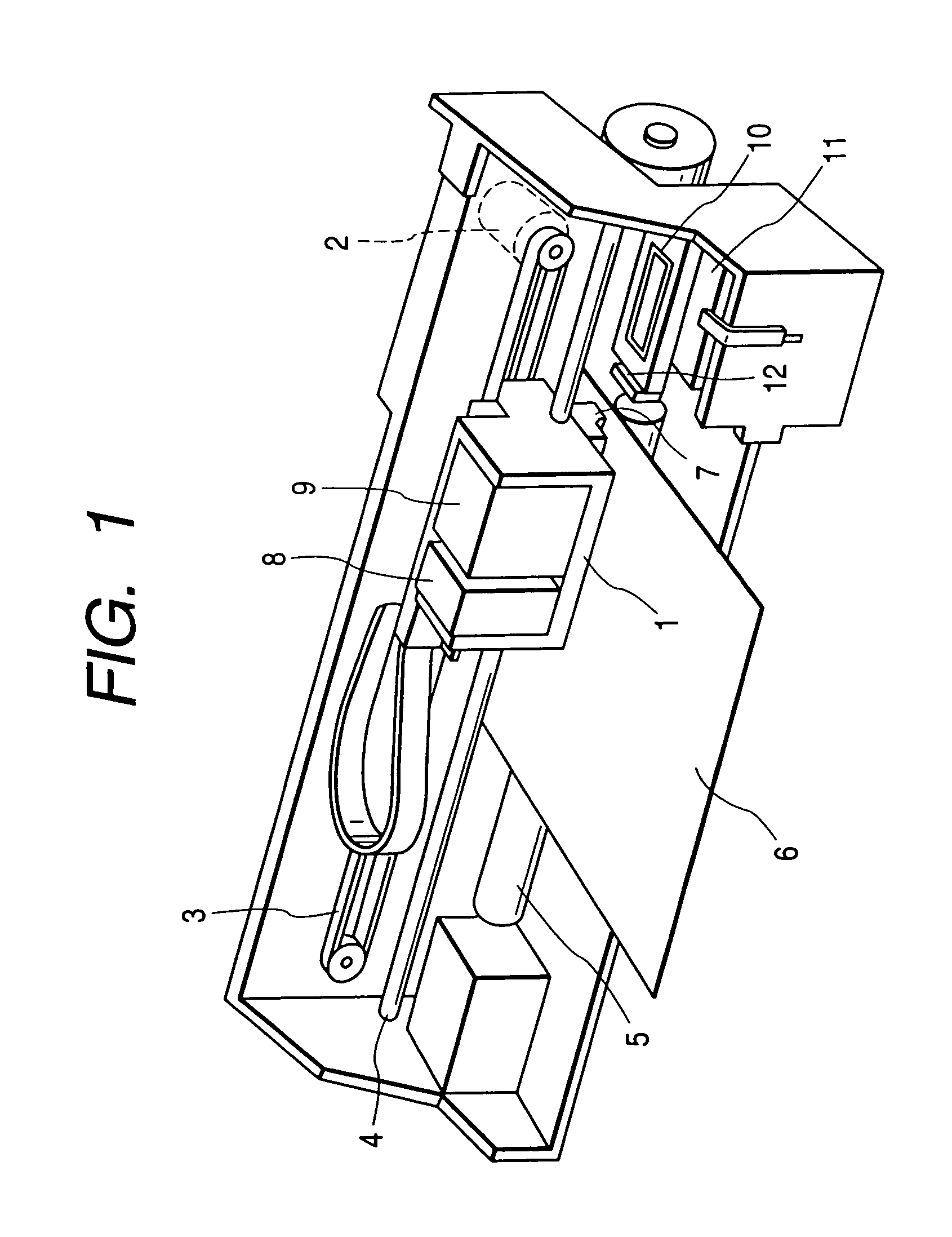
[0320]First, the cleaning sequence controller 45 sends a control signal to the carriage driver 49, whereby the carriage 1 is driven along a guide shaft 4 and is moved to the home position side.

[0321]Thus, at step S11, the wiping member 12 wip...

third embodiment

[0350]In the control sequence in the invention shown in FIG. 10, steps S31 to S33 are executed in place of steps S15 and S16 shown in FIG. 8.

[0351]That is, when the recording head 7 is capped and the atmospheric valve 26 is closed at steps S13 and S14, driving the suction pump 11 is started at step S31 following step S14.

[0352]Thus, negative pressure is given to the internal space of the capping unit.

[0353]In this state, at step S32, a wait is made for expiration of a third predetermined time and if it is determined that the third predetermined time has elapsed, the valve unit 36 is closed at step S33.

[0354]Subsequently, a control sequence similar to that at steps S17 and later previously described with reference to FIG. 8 is executed.

[0355]If the control sequence in the third embodiment shown in FIG. 10 is adopted, the suction pump is driven early, so that the negative pressure in the internal space of the capping unit can be raised rapidly.

[0356]Next, FIG. 11 shows a control seque...


PUM


Abstract

A valve unit 36 is placed in an ink flow passage 35 between an ink cartridge 8 and a recording head 7 and can be controlled in association with the cleaning operation of the recording head 7. Under the control of a drive controller, the valve unit 36 holds for a predetermined time a state in which negative pressure produced by a suction pump is accumulated, and is opened after the expiration of the predetermined time or is opened with the negative pressure accumulated and driving the suction pump is continued. The air bubbles remaining in a stuck state in the ink flow passage can be peeled from the ink flow passage together with an instantaneous fast ink flow produced as the valve unit 36 is opened, and the peeled air bubbles can be discharged, effectively from the ink flow passage following the subsequent ink flow.

Description

BACKGROUND OF THE INVENTION[0001]This invention relates to an ink jet recording apparatus comprising a recording head moving in a width direction of recording paper for jetting ink drops toward recording paper based on print data, thereby printing an image on the recording paper and a control technique of cleaning of the recording head for sucking ink from nozzle orifices of the recording head of the recording apparatus for recovering the print function of the recording head.[0002]An ink jet recording apparatus, which produces comparatively small noise at the printing time and moreover can form small dots at a high density, is much used for printing including color printing in these days.[0003]Such an ink jet recording apparatus comprises an ink jet recording head for receiving supply of ink from an ink storage section of an ink cartridge mounted on a cartridge, a subtank, etc., and paper feeder for causing recording paper to make a relative move to the recording head. While moving ...

Claims


Application Information

Patent Timeline
Patent Type & Authority Patents(United States)
IPC IPC(8): B41J2/175B41J2/165B41J2/19
CPCB41J2/16532B41J2/19
Inventor HARADA, SHUHEIMIYAZAWA, HISASHIHAYAKAWA, HITOSHIKOBAYASHI, ATSUSHIKIMURA, HITOTOSHIARUGA, YOSHIHARU
Owner SEIKO EPSON CORP
Why Eureka
Try Eureka