Method of driving pump

a technology of pump and drive shaft, which is applied in the direction of machines/engines, liquid fuel engines, positive displacement liquid engines, etc., can solve the problems that the size of the pump affects the output seriously, and achieve the effect of enhancing the reliability of an actuator and a pump and high pumping outpu

Active Publication Date: 2006-10-17
SEIKO EPSON CORP
View PDF5 Cites 4 Cited by
  • Summary
  • Abstract
  • Description
  • Claims
  • Application Information

AI Technical Summary

Benefits of technology

[0013]According to the invention, a high pumping output can be attained regardless of pump size by increasing an output by using an inertia effect of a fluid caused by the large inertance at an outlet passage.
[0016]According to the invention, a pumping output with a double multiplied wave mode described later can be attained regardless of pump size. If it is driven by a double multiplied wave mode, the endurance of a check valve is improved so as to enhance the reliability of a pump.
[0020]In addition, the driving waveform of a piston or a diaphragm is preferably an approximate sine wave. According to the invention, it is easy to attain a driving circuit with an internal stress generated in an actuator while driving can be small so as to enhance the reliability of an actuator and a pump.

Problems solved by technology

There is a problem in that the change of the inertia effect caused by the change of a driving waveform of a piston or a diaphragm or a pump size affects the output seriously.

Method used


Image

  • Method of driving pump
  • Method of driving pump
  • Method of driving pump

Examples


Embodiment Construction

[0028]Embodiments of the invention will now be described with reference to the accompanying drawings.

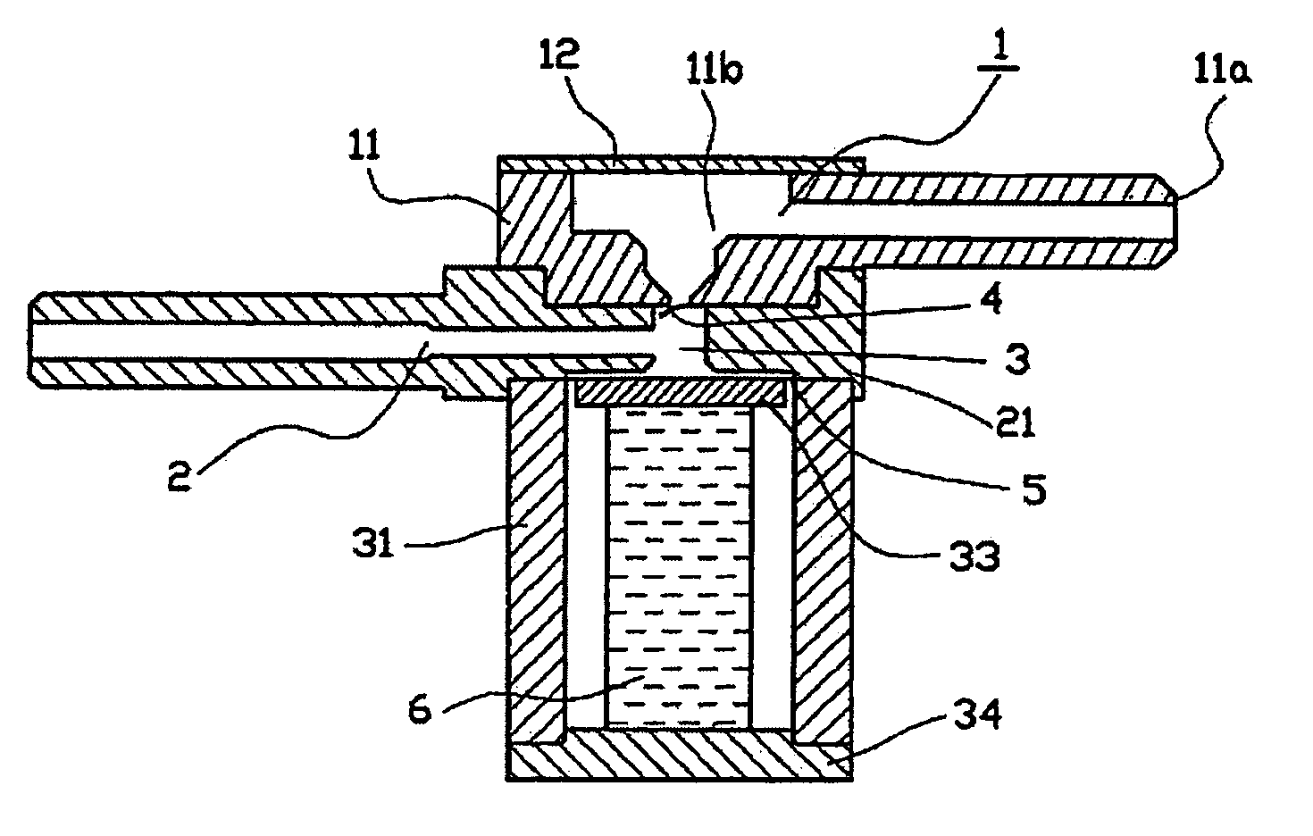
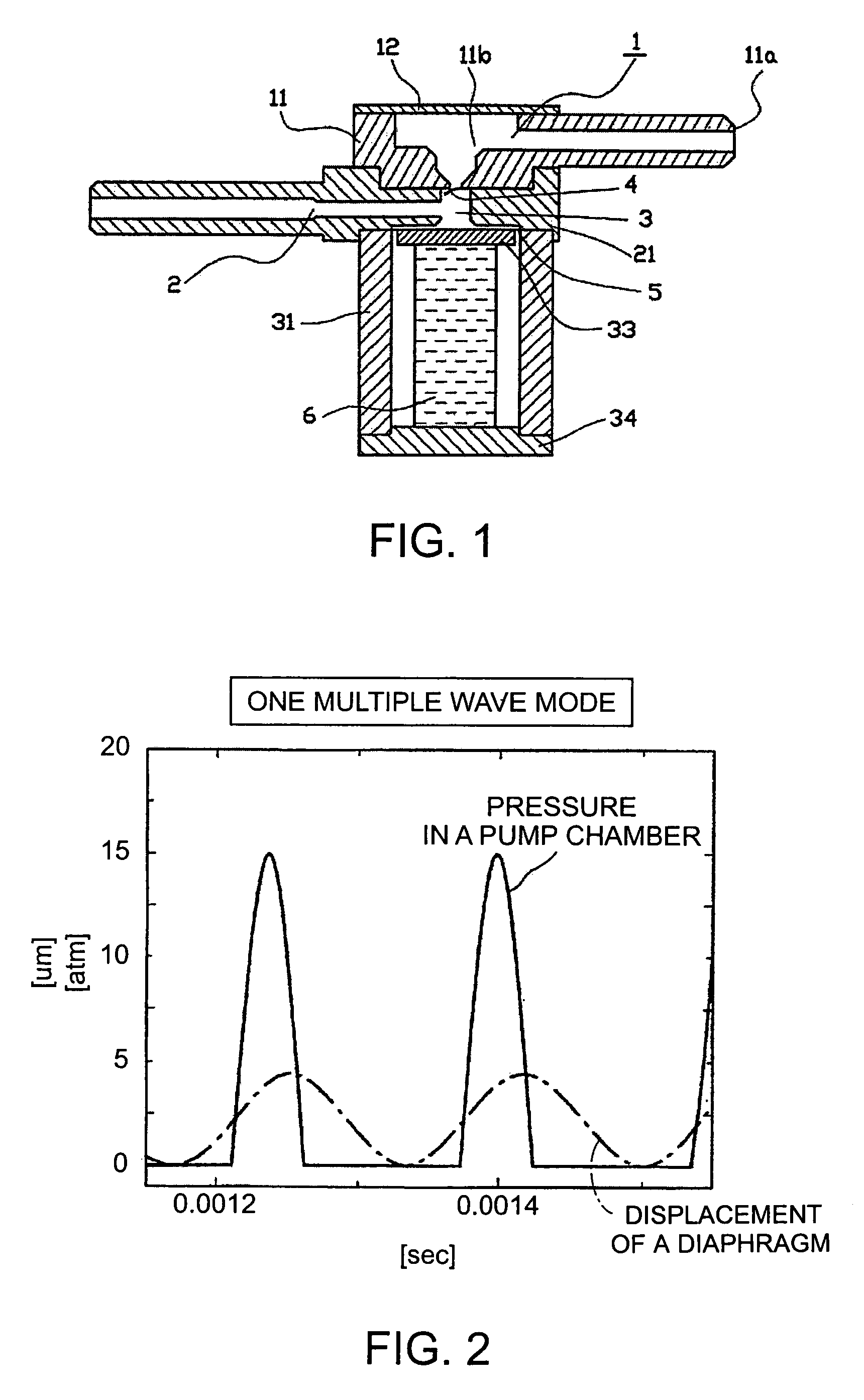
[0029]FIG. 1 shows a longitudinal cross section of a pump according to an embodiment of the present invention. A case bottom plate 34 is rigidly fixed by welding at the bottom of a piezoelectric element case 31, which is a member for supporting a multi layered type piezoelectric element 6. On the upper surface of the multi layered type piezoelectric element 6 as a driving source for a pump, an end plate 33 is adhered in advance so as to form a multi layered type piezoelectric element unit which is fixed within the piezoelectric element case 31. The fixing is preformed by adhering the bottom surface of the multi layered type piezoelectric element 6 with the case bottom plate 34.

[0030]After fixing the case bottom plate 34, the upper surface of the piezoelectric element case 31 is treated to be co-planar with the upper surface of the end plate 33 by a polishing process. A diaphragm 5 is...


PUM


Abstract

A pump is provided having a pump chamber that is capable of changing a volume thereof by a diaphragm, an inlet passage permitting an operating fluid to flow into the pump chamber; an outlet passage permitting an operating fluid to flow out from the pump chamber; and a check valve provided on the inlet passage. An inertance value of the inlet passage is smaller than the inertance value of the outlet passage. The diaphragm is driven by a frequency f (Hz) satisfying the following formula:f≥0.26X⁢L⁢⁢Swherein the inertance value of the outlet passage is L (kg / m4), the displacement from an upper end point to a bottom end point of the diaphragm is X (m), and the cross section area of the pump chamber is S (m2).

Description

RELATED APPLICATIONS[0001]This application claims priority to Japanese Patent Application No. 2003-364739 filed Oct. 24, 2003 which is hereby expressly incorporated by reference herein in its entirety.BACKGROUND[0002]1. Technical Field[0003]The present invention relates to a small-sized pump that moves a liquid by changing a volume inside a pump chamber through a piston or a diaphragm and the like.[0004]2. Related Art[0005]There has been proposed a high output pump having a piston or a diaphragm driven by a piezoelectric element such as a PZT, a pump chamber capable of changing the volume by the diaphragm or the piston, an inlet passage to permit an operating fluid to flow into the pump chamber; an outlet passage to permit the operating fluid to flow out of the pump chamber; and a fluid resistance element such as a check valve provided on the inlet passage and the outlet passage. In this pump, an inertance value of the inlet passage is smaller than the inertance value of the outlet ...

Claims


Application Information

Patent Timeline
Patent Type & Authority Patents(United States)
IPC IPC(8): F04B17/00B81B3/00F04B19/00F04B43/02F04B43/04F04B49/06F04B53/10
CPCF04B19/006F04B53/1077
Inventor TAKAGI, KUNIHIKOSETO, TAKESHIYOSHIDA, KAZUHIRO
Owner SEIKO EPSON CORP
Why Eureka
Try Eureka