Vehicle parking assistance electronic timer system and method

a technology of electronic timer and vehicle parking assistance, which is applied in the field of electronic timer system and method, can solve the problems of lack of timely, updated information or reminders regarding the appropriate regulations, increased cost, and increased cost, and achieves the effect of drivers, and reducing the number of vehicles

Inactive Publication Date: 2006-10-17
RANAVERDE TECH INITIATIVE LLC
View PDF30 Cites 45 Cited by
  • Summary
  • Abstract
  • Description
  • Claims
  • Application Information

AI Technical Summary

Benefits of technology

[0009]According to an example embodiment of the present invention, an electronic timer device and an associated base unit may be programmed to remind the owner of a car of day(s) and / or time(s) that parking restrictions are in effect, for example, alternate side of the street parking restrictions. The electronic timer device may store predetermined information regarding the street name, locations, days and hours that parking is permitted or restricted based on municipal or other regulations, rules, and / or ordinances. By comparing this predetermined information to the present time and date, the electronic timer device may remind the user when and where to park his or her vehicle.
[0011]A honing device may be provided so that activation of the base unit may cause the electronic timer device to provide an alert to aid in finding lost keys or other articles attached to the electronic timer device. Rechargeable batteries may be provided in the electronic timer device with a recharger unit located in the base unit. The electronic timer device may provide an alert when battery charge is nearly depleted and as a reminder to recharge the battery. The memory of electronic timer device may be non-volatile to prevent data loss.

Problems solved by technology

Owning and operating a motor vehicle may be expensive, and with the cost of parking tickets and other avoidable fines and citations, the cost may be significantly increased.
Lack of timely, updated information or reminders regarding the appropriate regulations may be a problem for some drivers who are already juggling many other responsibilities.

Method used


Image

  • Vehicle parking assistance electronic timer system and method
  • Vehicle parking assistance electronic timer system and method
  • Vehicle parking assistance electronic timer system and method

Examples


Embodiment Construction

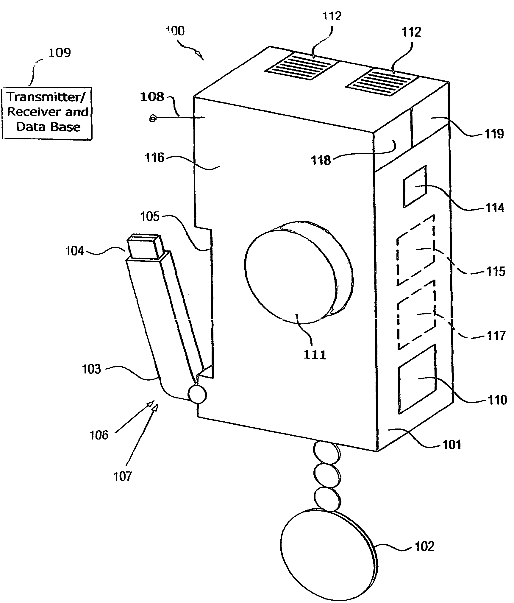
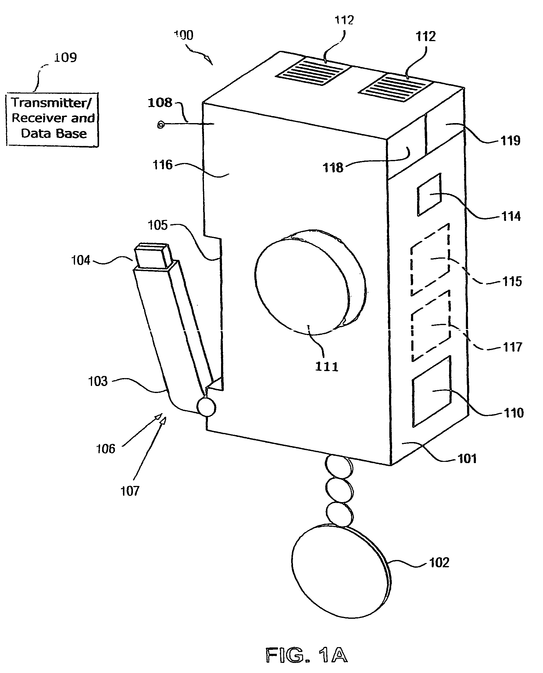
[0056]An exemplary embodiment of an electronic timer device 100 is shown in FIG. 1A. The housing 101 of the electronic timer device 100 may be formed of a durable and / or waterproof material, such as plastic or metal, so that it may withstand being accidentally dropped or stepped on, and protect the internal components from the environment, for example, rain. The housing 101 may be formed from any material that may be constructed, for example, molded or extruded, to form such a covering. The housing 101 may be in the shape of, for example, a rectangle similar in dimension to a credit card. The housing 101 may be formed so that it is, for example, one half of an inch to one inch thick. Other shapes are possible, and the housing 101 may be formed into any shape that will allow for the inclusion of the other features of the electronic timer device 100. The housing 101 may be changeable, so that the user may select from housings of different colors and artistic designs in order to coordi...


PUM


Abstract

An electronic timer system includes a first unit. The first unit includes a memory device configured to store predetermined parking rule data, a timer device configured to determine at least one of a day, a date and a time of day, and an alert device configured to emit an alert in accordance with the predetermined parking rule data and based on at least one of the day, the date and the time of day determined by the timer device. A method includes storing predetermined parking rule data in a memory device, determining at least one of a day, a date and a time of day, and emitting an alert in accordance with the predetermined parking rule data stored in the storing step and at least one of the day, the date and the time of day determined in the determining step.

Description

CROSS-REFERENCE TO RELATED APPLICATIONS[0001]The present application claims the benefit of U.S. non-provisional patent application Ser. No. 10 / 678,195 filed Oct. 2, 2003 now U.S. Pat. No. 7,023,360 which is expressly incorporated herein in its entirety by reference thereto which, in turn, claimed the benefit of U.S. provisional Patent Application No. 60 / 416,555, filed on Oct. 7, 2002, which was expressly incorporated therein in its entirety by reference thereto. The present application is related to Disclosure Documents Nos. 517,091, 517,466, 519,560 and 534,245, filed in the United States Patent and Trademark Office, each of which is expressly incorporated herein in its entirety by reference thereto.FIELD OF THE INVENTION[0002]The present invention relates to an electronic timer system and method.BACKGROUND INFORMATION[0003]Owning and operating a motor vehicle may be expensive, and with the cost of parking tickets and other avoidable fines and citations, the cost may be significant...

Claims


Application Information

Patent Timeline
Patent Type & Authority Patents(United States)
IPC IPC(8): B60Q1/48G07B15/02G07C1/30G08G1/14
CPCG07C1/30G08G1/14
Inventor STANISZEWSKI, JOHN T.
Owner RANAVERDE TECH INITIATIVE LLC
Why Eureka
Try Eureka