Method and system for antenna interference cancellation

a technology of antenna interference and cancellation method, applied in the field of wireless communication, can solve the problems of reducing the performance of either or both antennas, limiting bandwidth, and degrading signal fidelity, so as to enhance bandwidth or information carrying capacity, improve signal quality, and improve signal quality

Inactive Publication Date: 2006-10-17
INTERSIL INC
View PDF279 Cites 86 Cited by
  • Summary
  • Abstract
  • Description
  • Claims
  • Application Information

AI Technical Summary

Benefits of technology

[0014]The present invention supports compensating for signal interference, such as crosstalk, occurring between two antennas or among more than two antennas. Compensating for crosstalk can improve signal quality and enhance bandwidth or information carrying capability in a wireless communication system.
[0016]In one aspect of the present invention, a cancellation device can apply a cancellation signal to the recipient antenna, which typically receives an interference signal imposed by the transmitting antenna. The cancellation signal can suppress, cancel, reduce, minimize, or negate, or otherwise compensate for, the interference signal, thereby enhancing isolation between the antennas and improving performance. The cancellation device can generate, compose, or produce the cancellation signal based on signals sampled or tapped either from the transmitting antenna or from the recipient antenna.
[0017]In another aspect of the present invention, the cancellation device can generate the cancellation signal by sampling the interference signal from the recipient antenna and processing the sample signal. Processing the sample signal can comprise adjusting the phase and the amplitude of the sample signal with a signal processing circuit to provide a cancellation signal that matches the interference signal. Adjusting the phase and amplitude of the sample signal can comprise slightly delaying in time an oscillation or cycle of the signal or slightly impeding the speed of propagation of the sample signal, for example with a variable phase adjuster. Adjusting the amplitude of the sample signal can comprise amplifying, scaling, or intensifying the sample signal, for example with a variable gain amplifier. The cancellation device can apply the cancellation signal to the recipient antenna to cancel the interference signal carried thereon. For example, the cancellation device can subtract the cancellation signal from the interference signal via a coupler that introduces the cancellation signal onto a feed line of the recipient antenna. The cancellation device can comprise a controller that dynamically controls, tunes, or adapts the phase and amplitude adjustments to refine or update the effectiveness of the interference cancellation. The cancellation device can gauge cancellation effectiveness by monitoring the level of residual or un-cancelled interference energy that exists on the recipient antenna following cancellation. The controller can use the monitored energy or power level as a feedback signal for refining the phase and amplitude adjustments. During interference cancellation, the recipient antenna can be in a dormant or passive state, for example refraining from transmitting communication signals, while the transmitting antenna is in an active state of transmitting communication signals.
[0018]In another aspect of the present invention, the cancellation device can generate a cancellation signal by sampling the communication signal on the transmitting antenna and processing that sample signal. Processing the sample signal can comprise feeding the sample signal into a model of the interference effect. The model can generate and output the cancellation signal as an estimate or emulation of the interference signal. The cancellation device can cancel a substantial portion of the interference by applying the cancellation signal to the recipient antenna, for example, by subtracting the cancellation signal from the signals that the recipient antenna carries. The cancellation device can comprise a controller that dynamically adjusts or adapts the model to refine the cancellation signal, thereby increasing cancellation effectiveness or maintaining cancellation effectiveness in a dynamic operating environment. The controller can monitor residual interference energy on the recipient antenna and adjust the model to minimize the monitored energy. The cancellation device can inject test signals into the antenna system and monitor the interference that these test signals produce. The controller can analyze interference stimulated by the test signals and refine the model based on the analysis.

Problems solved by technology

A communication signal transmitting on one antenna can couple or impose an unwanted signal, such as interference or crosstalk, onto another antenna.
In a wireless communication system, such coupling can interfere with and degrade the performance of either or both antennas, for example limiting bandwidth or degrading signal fidelity.

Method used


Image

  • Method and system for antenna interference cancellation
  • Method and system for antenna interference cancellation
  • Method and system for antenna interference cancellation

Examples


first embodiment

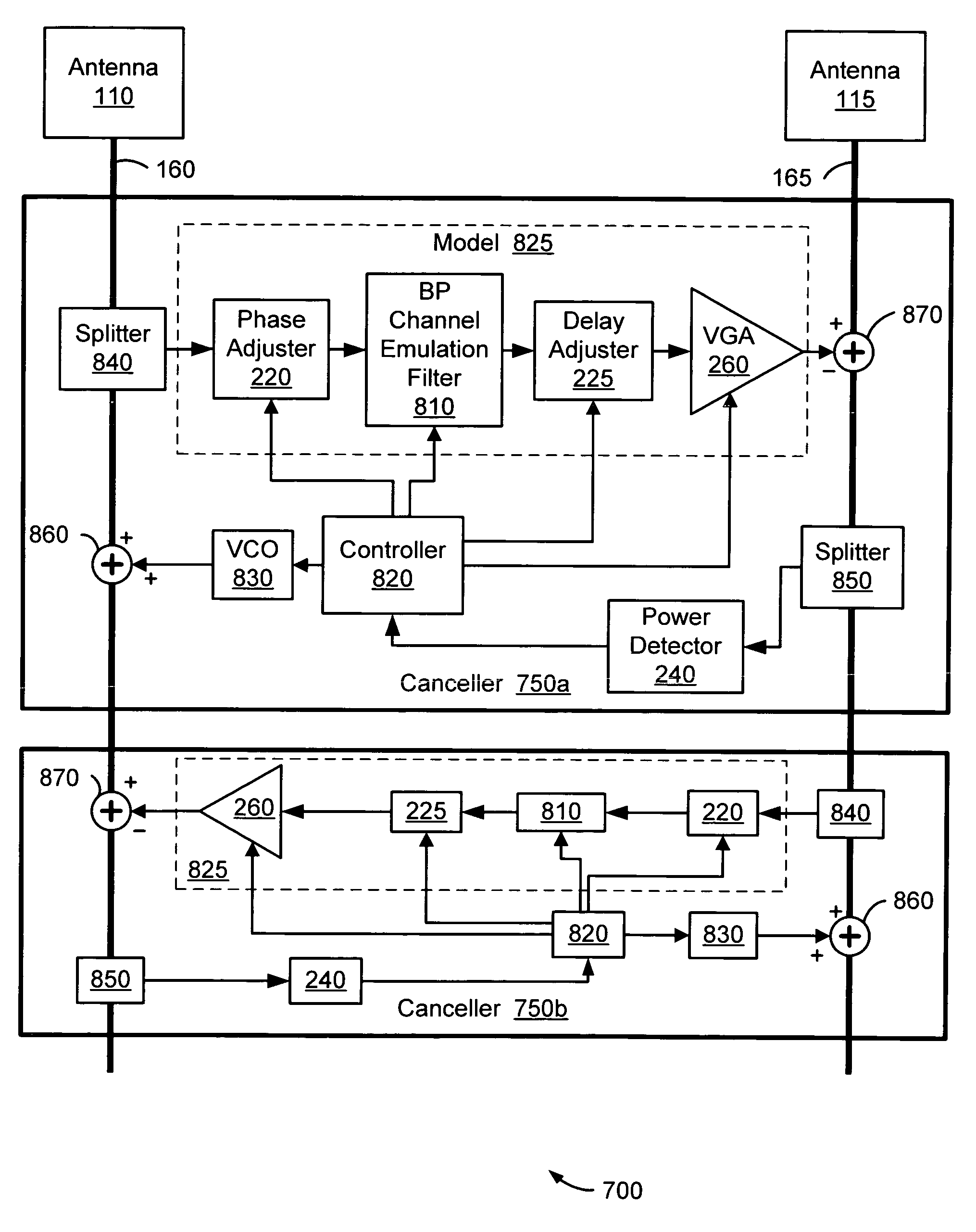
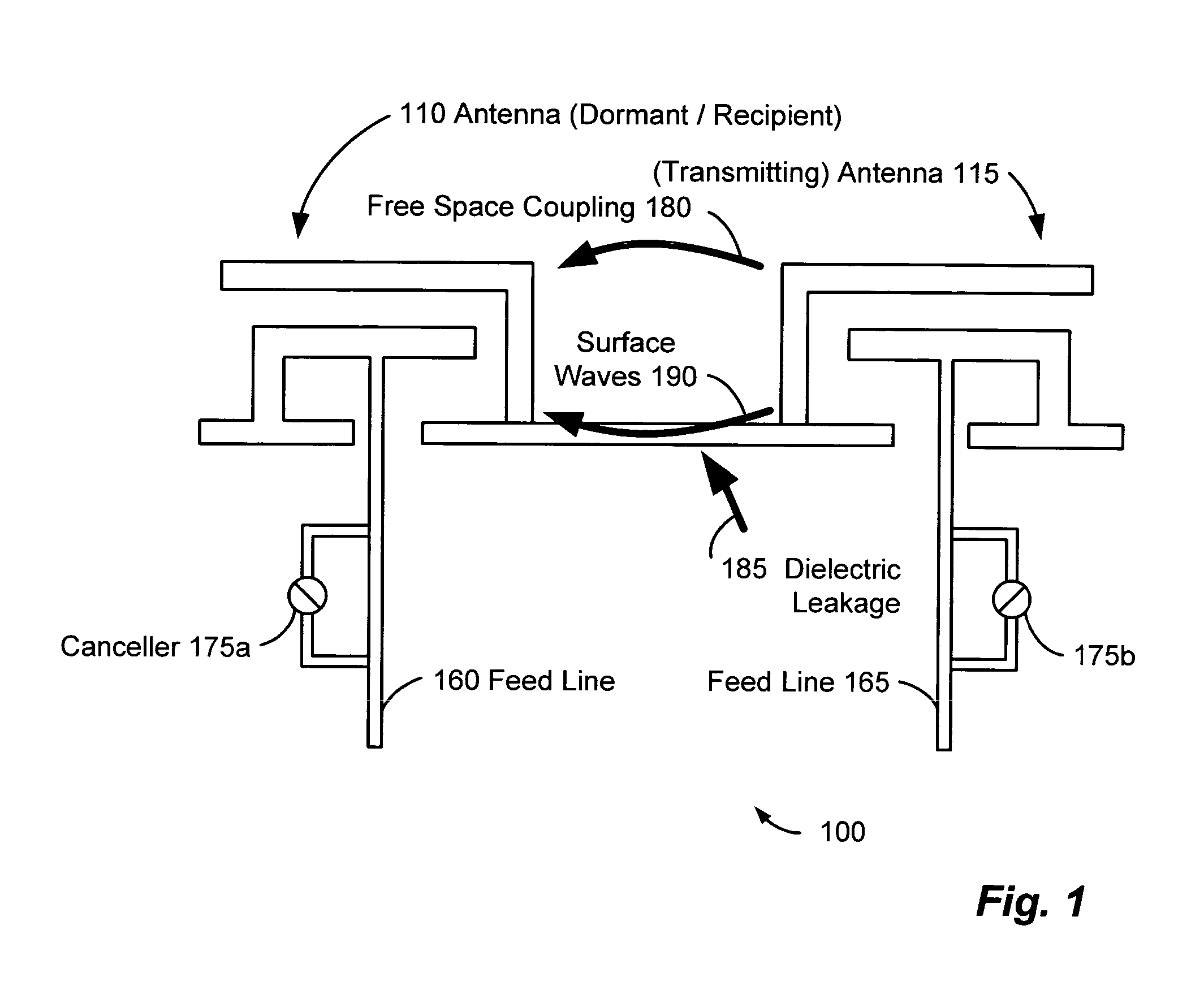
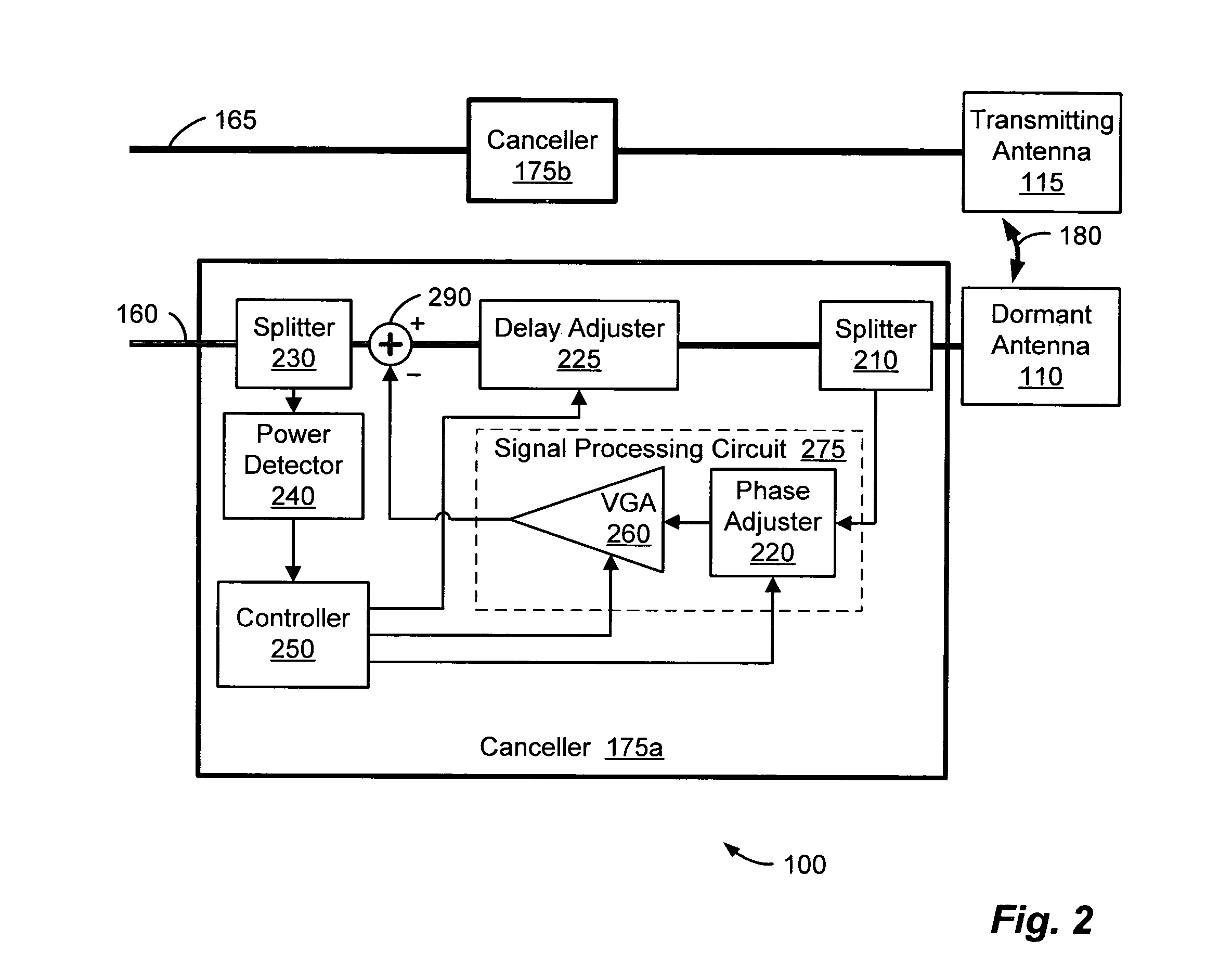
[0119]Exemplary embodiments of the system 700 can provide interference cancellation in three operational states. In one embodiment, the system 700 operates in a diversity antenna application, whereby the antenna 115 is dormant and the antenna 110 is actively transmitting. In such a diversity application, the canceller 750a can cancel crosstalk imposed on recipient antenna 115 without using pilot signals to characterize the coupling channel. Thus, this first embodiment can correspond to the modes of operation of the system 100 illustrated in FIGS. 1 and 2 and discussed above.

second embodiment

[0120]In a second embodiment, the system 700 operates with the antenna 115 and the antenna 110 operating at distinct frequencies. In this scenario, the communication signals transmitting on the antenna 110 couple onto the antenna 115 via a coupling channel. The canceller 750a injects two pilot signals onto the antenna 110, which couple onto the antenna 115. One of these pilot signals has a frequency above the operating frequency of antenna 115, while the other pilot signal has a frequency below the operating frequency of the antenna 115. The canceller uses these pilot signals to address the interference.

[0121]In the third embodiment, the canceller 750 cancels crosstalk occurring with the antenna 110 and the antenna 115 operating at essentially the same frequency. The third exemplary embodiment will be discussed in detail. Those skilled in the art will appreciate the applicability of the discussion to the second embodiment described in the immediately preceding paragraph.

[0122]With t...


PUM


Abstract

A wireless communication system can comprise two or more antennas that interfere with one another via free space coupling, surface wave crosstalk, dielectric leakage, or other interference effect. The interference effect can produce an interference signal on one of the antennas. A cancellation device can suppress antenna interference by generating an estimate of the interference signal and subtracting the estimate from the interference signal. The cancellation device can generate the estimate based on sampling signals on an antenna that generates the interference or on an antenna that receives the interference. The cancellation device can comprise a model of the crosstalk effect. Transmitting test signals on the communication system can define or refine the model.

Description

CROSS REFERENCE TO RELATED APPLICATIONS[0001]This application claims the benefit of priority to U.S. Provisional Patent Application Ser. No. 60 / 520,592, entitled “Improved Performance of Closely Spaced Antennas,” and filed Nov. 17, 2003. The contents of U.S. Provisional Patent Application Ser. No. 60 / 520,592 are hereby incorporated by reference.[0002]This application is related to U.S. Nonprovisional patent application Ser. No. 10 / 108,598, entitled “Method and System for Decoding Multilevel Signals,” filed on Mar. 28, 2002, and U.S. Nonprovisional patent application Ser. No. 10 / 620,477, entitled “Adaptive Noise Filtering and Equalization for Optimal High Speed Multilevel Signal Decoding,” filed on Jul. 15, 2003, and U.S. Nonprovisional patent application Ser. No. 10 / 911,915, entitled “Method and System for Crosstalk Cancellation,” filed on Aug. 5, 2004. The contents of U.S. patent application Ser. No. 10 / 108,598 and U.S. patent application Ser. No. 10 / 620,477 and U.S. patent applica...

Claims


Application Information

Patent Timeline
Patent Type & Authority Patents(United States)
IPC IPC(8): H04L7/06H01Q1/52H04B1/10H04B1/12H04B1/52H04LH04L1/00H04L1/24H04L7/00
CPCH01Q1/521H01Q1/525H04B1/1027H04B1/1036H04B1/126H04B1/525H04B7/15585H04L1/24H04L7/00H01Q3/30H04B1/10H04Q1/24
Inventor GEBARA, EDWARDLASKAR, JOYTENTZERIS, EMMANOUIL M.KIM, ANDREW JOO
Owner INTERSIL INC
Why Eureka
Try Eureka