Split transaction reordering circuit

a transaction bus and circuit technology, applied in the direction of electric digital data processing, instruments, etc., can solve the problems of plurality of transferred requests, atomic bus may potentially waste bus cycles, bus to stall waiting for resources to no longer be used,

Inactive Publication Date: 2006-10-17
CISCO TECH INC
View PDF11 Cites 35 Cited by
  • Summary
  • Abstract
  • Description
  • Claims
  • Application Information

AI Technical Summary

Benefits of technology

[0010]The present invention is directed to a technique for ordering responses received by a network device over a split transaction bus, such as a HyperTransport bus (HPT). According to the invention, an intermediate “assist” device, e.g. within a DMA controller, receives responses from one or more target devices located over the bus and forwards the responses in a predetermined order to their requesting sources. Thus, the process of reordering responses is off-loaded to the intermediate device without having to consume bandwidth and resources within the target devices and / or sources.

Problems solved by technology

However, an atomic bus may potentially waste bus cycles, particularly when waiting for data in response to, e.g., a read request.
It is possible that some of the resources may be consumed by these transfers, thereby causing the bus to stall waiting on the resources to no longer be in use (freed).
This stall, in turn, may result in a plurality of transferred requests concurrently awaiting responses (i.e., “outstanding”) over the split transaction bus.
Responses to pending requests are additionally limited by the inherent latency of accessing memory locations over the bus.
When a plurality of requests are outstanding, memory access delays may result in responses arriving “out of order.” That is, the responses may be received in a different order than their corresponding requests.
Unordered responses may therefore inhibit proper construction of a received information packet.
However, resources configured to implement an ordering scheme in a target device may limit the device's “read” bandwidth, i.e. how quickly data is retrieved from memory.
In those situations where requesting sources are configured to reorder responses received from a split transaction bus, each source must consume resources and bandwidth to implement the ordering protocol.

Method used


Image

  • Split transaction reordering circuit
  • Split transaction reordering circuit
  • Split transaction reordering circuit

Examples


Embodiment Construction

A. Intermediate Nodes in a Network

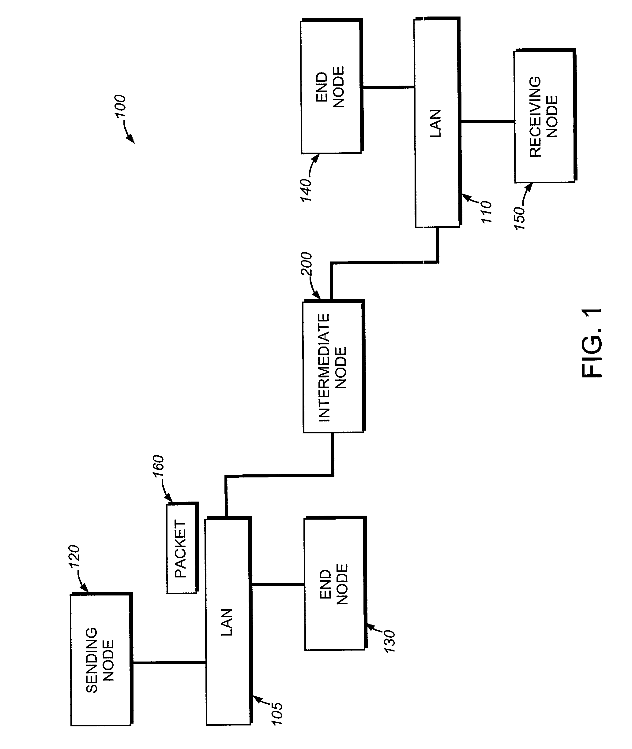
[0031]FIG. 1 is a block diagram of a computer network 100 comprising a collection of interconnected subnetworks and nodes. The nodes may comprise computers including end nodes 130 and 140, such as a sending end node 120 and a receiving end node 150, and an intermediate network node 200, the latter of which may be a switch or router. The subnetworks 105, 110 included within network 100 are preferably local area networks (LANs) interconnected by the intermediate node 200, although the networks may comprise other communication links, such as wide area networks. Communication among the nodes coupled to the LANs is typically effected by exchanging discrete packets 160 among the nodes.

[0032]For example, the sending node 120 generates a data packet 160 by encapsulating “payload” data within headers, such as conventional data link and network layer headers, as the data passes through different layers of a protocol stack. The packet is then transmitted over ...


PUM


Abstract

The present invention provides a technique for ordering responses received over a split transaction bus, such as a HyperTransport bus (HPT). When multiple non-posted requests are sequentially issued over the split transaction bus, control logic is used to assign each request an identifying (ID) number, e.g. up to a maximum number of outstanding requests. Similarly, each response received over the split transaction bus is assigned the same ID number as its corresponding request. Accordingly, a “response memory” comprises a unique memory block for every possible ID number, and the control logic directs a received response to its corresponding memory block. The responses are extracted from blocks of response memory in accordance with a predetermined set of ordering rules. For example, the responses may be accessed in the same order the corresponding non-posted requests were issued.

Description

FIELD OF THE INVENTION[0001]This invention relates generally to split transaction buses, and more specifically, to maintaining order among responses received over a split transaction bus.BACKGROUND INFORMATION[0002]A computer network is a geographically distributed collection of interconnected subnetworks for transporting data between nodes, such as computers. A local area network (LAN) is an example of such a subnetwork; a plurality of LANs may be further interconnected by an intermediate network node, such as a router or switch, to extend the effective “size” of the computer network and increase the number of communicating nodes. The nodes typically communicate by exchanging discrete frames or packets of data according to predefined protocols. In this context, a protocol consists of a set of rules defining how the nodes interact with each other.[0003]Each node typically comprises a number of basic systems including a processor, a main memory and an input / output (I / O) system. Data ...

Claims


Application Information

Patent Timeline
Patent Type & Authority Patents(United States)
IPC IPC(8): G06F13/36
CPCG06F13/4059
Inventor GARNER, TREVORPOTTER, KENNETH H.WU, HONG-MAN
Owner CISCO TECH INC
Why Eureka
Try Eureka