Anchoring framework to a masonry wall

Inactive Publication Date: 2006-10-24
DEMING RICHARD ALLEN
View PDF26 Cites 27 Cited by
  • Summary
  • Abstract
  • Description
  • Claims
  • Application Information

AI Technical Summary

Benefits of technology

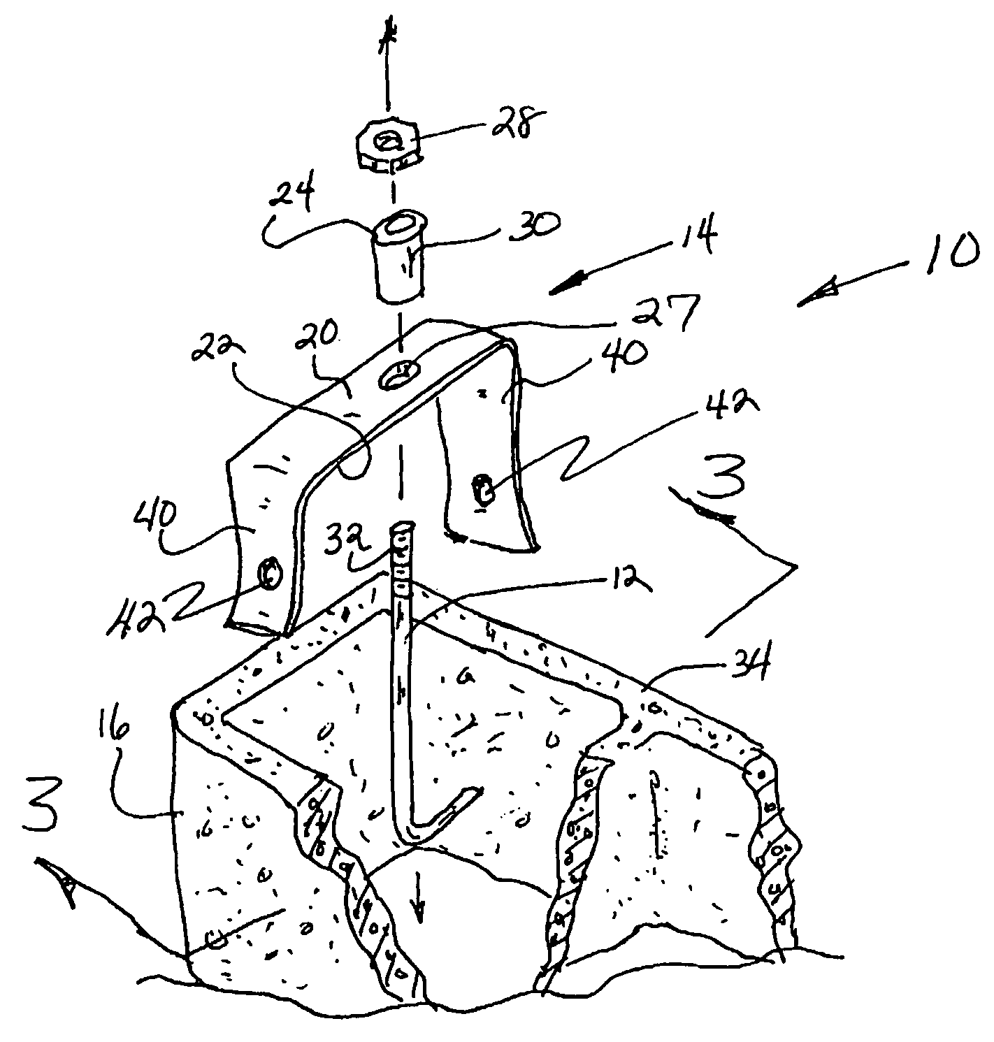
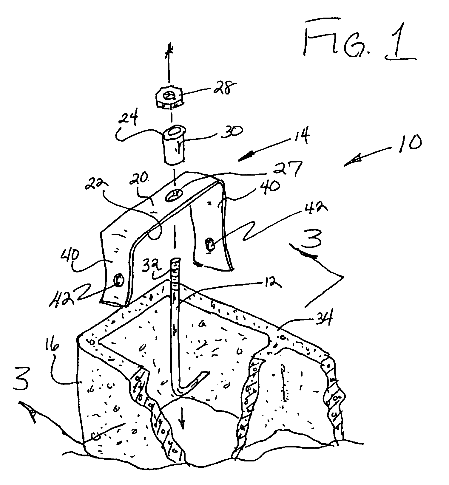
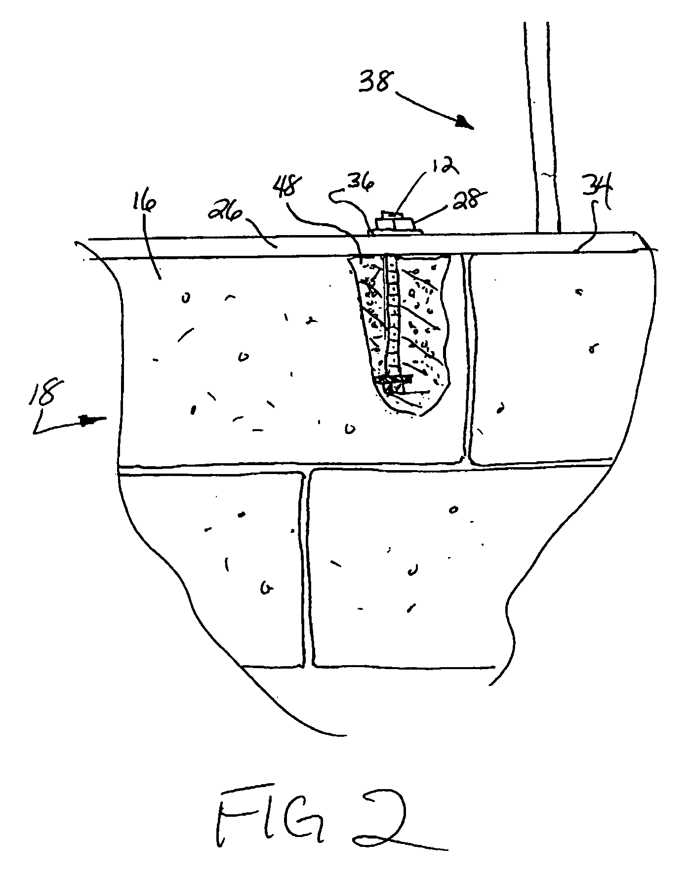
[0009]A preferred embodiment of the invention provides a method for connecting structural framework atop a concrete masonry wall that may be made up of several tows of blocks, each of which has at least one vertically disposed channel extending all the way through it. As is conventional in the art, a width of the masonry wall is the same as the predetermined width of each of the blocks. As is also conventional, the framework may comprise a sill plate portion made from a piece of lumber having a standard thickness. A preferred method of connecting the masonry wall to the framework involves using an anchor and an anchor

Problems solved by technology

If an anchor is tilted or displaced from its predetermined position, erection of the framework will be delayed until that anchor is cut off and possibly replaced.
Unfortunately, the prior art does not provide a reliable means for emplacing an entire array of anchors along a wall.
If anchors are emplaced by being manually inserted into wet, unset grout, some of those anchors may fall over into unacceptable orientations as the grout sets.
If anchors are vertically suspended from wire hangers prior to pouring the

Method used


Image

  • Anchoring framework to a masonry wall
  • Anchoring framework to a masonry wall
  • Anchoring framework to a masonry wall

Examples


Embodiment Construction

[0018]In studying this Detailed Description, the reader may be aided by noting definitions of certain words and phrases used throughout this patent document. Wherever those definitions are provided, those of ordinary skill in the art should understand that in many, if not most instances, such definitions apply to prior, as well as future uses of such defined words and phrases. At the outset of this Description, one may note that the terms “include” and “comprise,” as well as derivatives thereof, mean inclusion without limitation; the term “or,” is inclusive, meaning and / or. The term “framework” stands for any sort of structural framing using in building construction and comprises structural members made from lumber, steel, aluminum, or any other material or combination thereof; such framework may comprise prefabricated sub-assemblies brought to a job site, or may comprise a framework erected from individual pieces of lumber or other structural members at the job site. A lowest horiz...


PUM


Abstract

An upper framed portion of a building structure may be anchored to a lower masonry wall by using a conventional concrete anchor and an anchor retainer. The anchor retainer may have a body portion longer than the width of the wall and both upper and lower reference surfaces. An anchor retainer assembly is temporarily formed by inserting the anchor through a throughhole in the retainer body so that the threaded upper portion of the anchor extends above the upper reference surface of the retainer by a first selected height, so as to leave enough of the threaded end exposed above the retainer for at least one nut to be securely attached to the anchor. No unthreaded portion of the anchor extends above the lower reference surface by more than a second amount that is generally selected to be equal to the actual thickness of the framing member, so as to ensure that no substantial unthreaded portion of the anchor can extend above that member.

Description

BACKGROUND OF THE INVENTION[0001]1. Field of the Invention[0002]The invention relates to a tie or anchoring arrangement assembled in situ to anchor an upper framed portion of a building structure to a lower masonry wall portion[0003]2. Background Information[0004]Concrete masonry walls can be formed of vertically stacked concrete blocks having internal, vertical, mutually aligned cavities that form channels extending vertically through the wall. These may be reinforced by placing rebar through the vertically aligned cavities and filling the channels about the bars with a wet cementitious mixture known as grout. The grout, when set, locks the bars to the blocks and thus provides the wall with increased resistance to applied loads.[0005]Frame structures are often erected on top of reinforced or non-reinforced masonry walls. These may be roofs, wooden frame portions of composite walls, or a combination of a framed upper wall and a roof. Composite walls having a framed upper portion are...

Claims


Application Information

Patent Timeline
IPC IPC(8): E04C5/12E04B1/00E04G21/00
CPCE04B1/4157E04G21/185
Inventor DEMING, RICHARD ALLEN
Owner DEMING RICHARD ALLEN
Why Eureka
Try Eureka