Gimbal mechanism

a gimbal and mechanism technology, applied in the field of unique configuration of gimbal mechanisms, can solve the problems of low cost low utilization rate of such automated gimbal mechanisms, and low efficiency of use of automated gimbal mechanisms, so as to facilitate lateral positioning of gimbal mechanisms, facilitate frictional engagement, and facilitate the effect of mounting the gimbal mechanism

Inactive Publication Date: 2006-10-24
MILLER JERRY J
View PDF32 Cites 19 Cited by
  • Summary
  • Abstract
  • Description
  • Claims
  • Application Information

AI Technical Summary

Benefits of technology

[0009]Provided is a gimbal mechanism which is adapted to be angularly positionable about multiple axes of orientation as well as laterally positionable relative to a mounting surface upon which the gimbal mechanism may be mounted. The gimbal mechanism may be used to mount a variety of objects such as a surveillance camera lens such that the camera lens is easily adjustable over a wide field of view.
[0013]The outer frame may be pivotally connected to the support stand by a pair of mechanical fasteners such as a thumbscrew which extends through the first slots and engages a threaded hole in the outer frame sides. The thumbscrews are operative to cause slight relative axial motion between at least one of the first members and the adjacent one of the outer frame sides in order to facilitate frictional engagement of the first members to the outer frame sides in order to maintain or lock the angular and lateral position of the outer frame relative to the support stand. A pair of pivot mechanisms may connect at least one of the inner frame ends with an adjacent one of the outer frame ends in order to maintain the desired angular position of the inner frame relative to the outer frame.
[0014]The gimbal mechanism may include a base member extending between the second members. The base member may include a pair of base slots extending along a length of the base member. The base slots facilitate mounting of the gimbal mechanism to the mounting surface in such a manner as to facilitate lateral positioning of the gimbal mechanism relative to the mounting surface.

Problems solved by technology

Unfortunately, the open display of retail goods may result in a relatively high rate of theft from customers as well as from store personell.
Unfortunately, for situations where a relatively narrow field of view is required, the capability of such automated gimbal mechanisms is underutilized.
For example, in a retail situation where the area under surveillance is limited to the area surrounding a cash register, the use of an automated gimbal mechanism is not cost effective.
Unfortunately, such intricate surface features necessitate the use of precision machining or fabrication techniques.
Such gimbal mechanisms are therefore costly and time-consuming to manufacture.

Method used


Image

  • Gimbal mechanism
  • Gimbal mechanism
  • Gimbal mechanism

Examples


Embodiment Construction

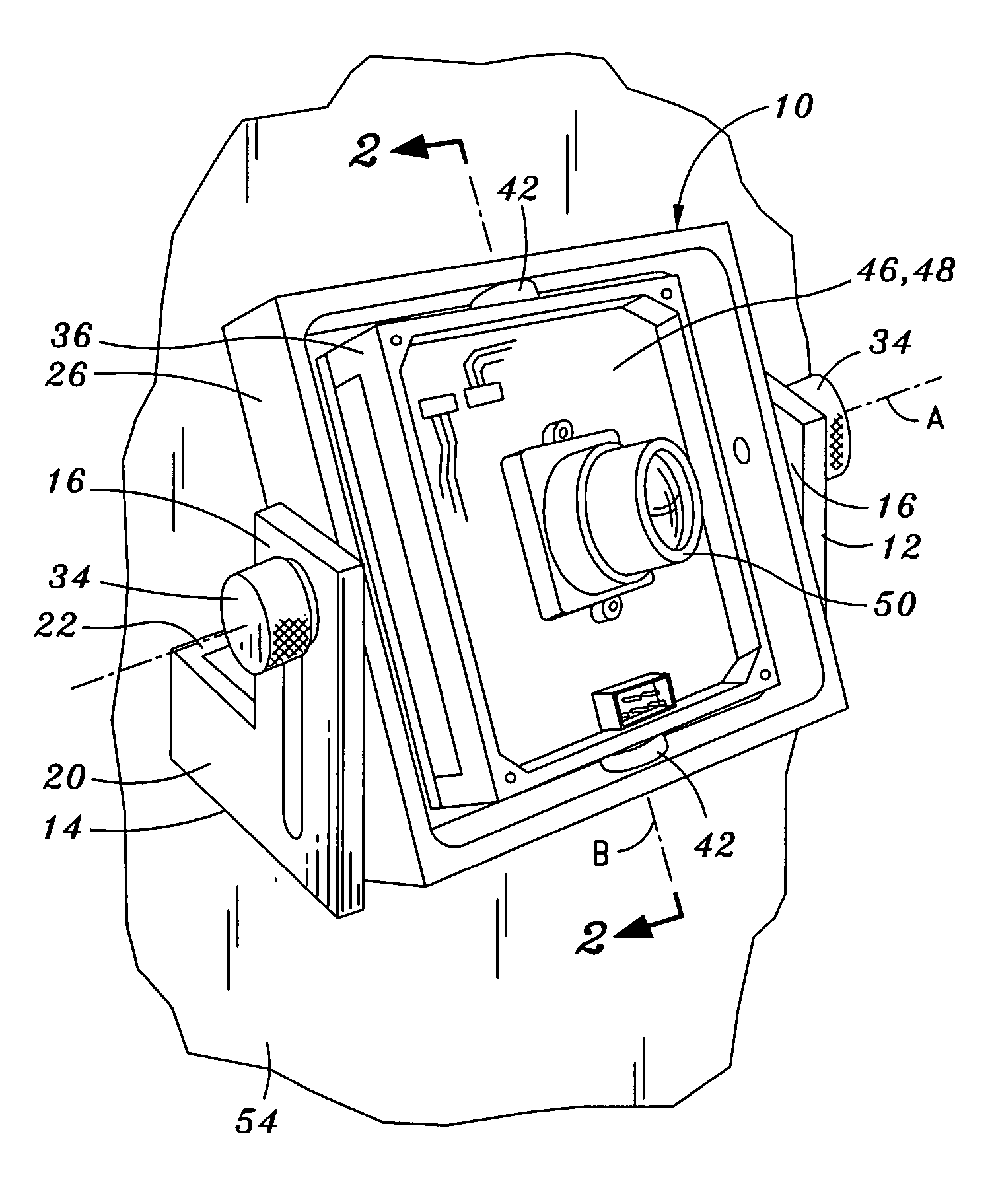
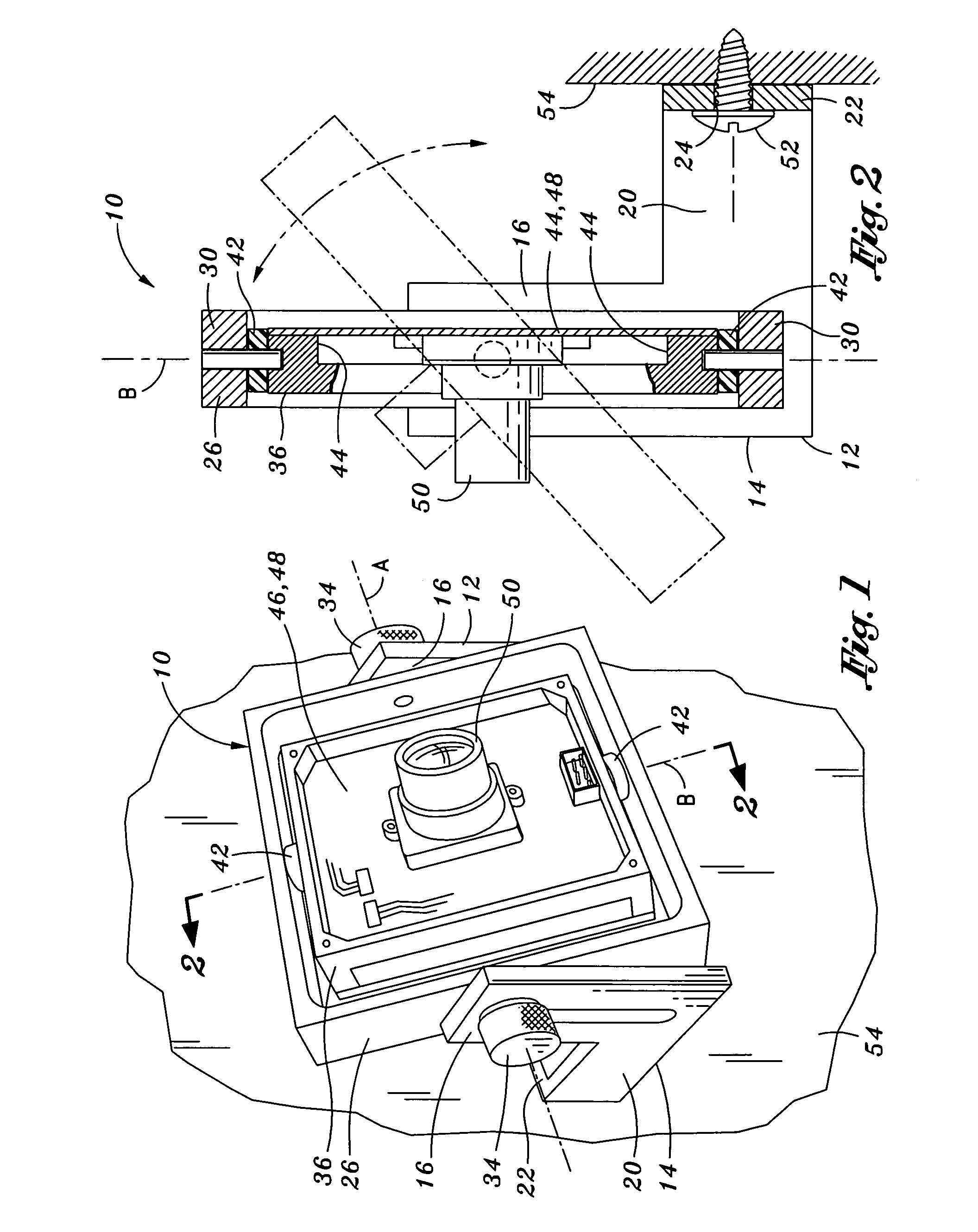
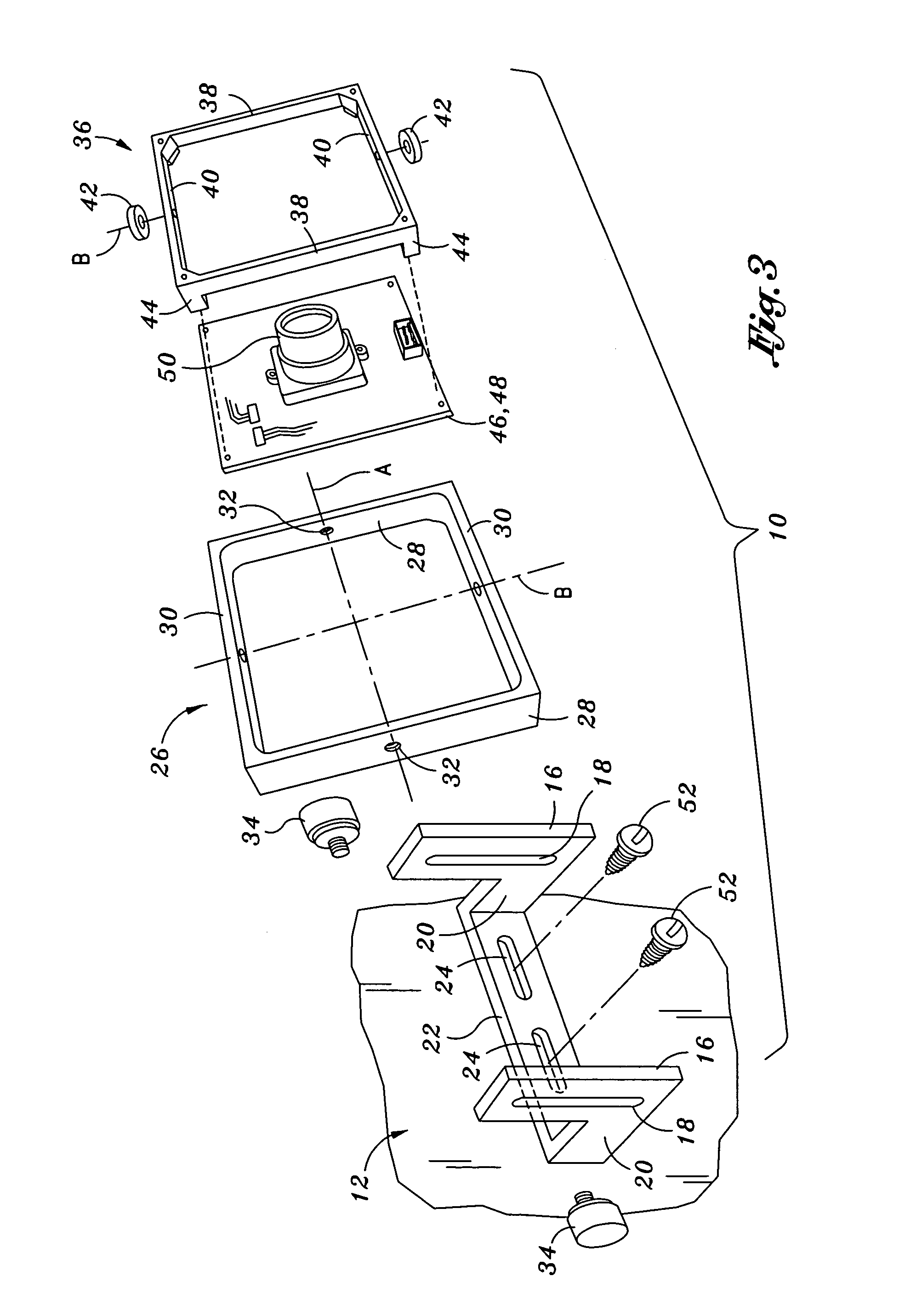
[0022]Referring now to the drawings wherein the showings are for purposes of illustrating the present invention and not for purposes of limiting the same, shown in FIGS. 1–6 is a gimbal mechanism 10 which is specifically adapted to be angularly positionable about multiple axes of orientation as well as laterally positionable relative to a mounting surface 54 upon which the gimbal mechanism 10 may be mounted. The gimbal mechanism10 may be used to mount a variety of objects including, but not limited to, a camera lens 50 such that the camera lens 50 is easily adjustable over a wide field of view.

[0023]In its broadest sense, the gimbal mechanism 10 is comprised of a support stand 12, an outer frame 26 and an inner frame 36. The support stand 12 may be mounted to the mounting surface 54 such as a wall or a ceiling of a building. However, the support stand 12 may be mounted to any suitable mounting member. The outer frame 26 is nested within and is pivotally connected to the support stan...


PUM


Abstract

Provided is a gimbal mechanism comprising a support stand, an outer frame and an inner frame. The support stand includes a spaced pair of L-shaped legs comprising a first member having at least one first slot formed therethrough. The outer frame is nested within the support stand and comprises outer frame sides joined to outer frame ends. Each one of the outer frame sides is pivotally engagable to the first slot of an adjacent one of the first members such that the outer frame is selectively angularly and laterally positionable relative to the support stand. The inner frame is nested within the outer frame and comprises inner frame ends joined to inner frame sides. Each one of the inner frame ends is pivotally engagable to an adjacent one of the outer frame ends such that the inner frame is selectively angularly adjusted relative to the outer frame about an inner frame axis.

Description

CROSS-REFERENCE TO RELATED APPLICATIONS[0001](Not Applicable)STATEMENT RE: FEDERALLY SPONSORED RESEARCH / DEVELOPMENT[0002](Not Applicable)BACKGROUND OF THE INVENTION[0003]The present invention relates generally to camera mounting systems and, more particularly, to a uniquely configured gimbal mechanism such as may be used to mount a surveillance camera and which is specifically adapted to be angularly positionable about multiple axes of orientation as well as laterally positionable relative to a mounting surface upon which the gimbal mechanism may be mounted.[0004]As a deterrent to crime, many residential and commercial buildings incorporate various security measures such as surveillance cameras which allow for remote detection, observation and recording of activity in a given area inside or outside of the building. One of the critical factors in the effectiveness of such surveillance cameras is the accuracy with which such cameras are directed toward areas where suspicious activity ...

Claims


Application Information

Patent Timeline
Patent Type & Authority Patents(United States)
IPC IPC(8): G01C19/24G01C19/44
CPCF16M11/08F16M11/12F16M11/2021F16M13/02Y10T74/1214Y10T74/1286Y10T74/1204
Inventor MILLER, JERRY J.
Owner MILLER JERRY J
Why Eureka
Try Eureka