Interlocking ring terminals

a technology of ring terminal which is applied in the direction of coupling contact members, coupling device connections, electrical devices, etc., can solve the problems of unreliable connection between wires and ring terminals, thermal events, and cold-softening of the plating on the terminals

Active Publication Date: 2006-10-24
AEES INC
View PDF8 Cites 36 Cited by
  • Summary
  • Abstract
  • Description
  • Claims
  • Application Information

AI Technical Summary

Benefits of technology

[0010]Preferably, each ring element includes a generally flat ring-like body, and the tabs are slightly offset, but generally parallel to, the ring-like bodies. The ring bodies are placed against each other and rotated so that the tabs move towards each other until the projection engages the opening. One ring element may include a collar about the central opening to assist in aligning the ring-like bodies.

Problems solved by technology

If three or more wires are crimped into a single grip, the wire(s) may be easily pulled out of the grip, creating an un-reliable connection between wire and ring terminal.
If more than two plated terminals are stacked together, the plating on the terminals may be subject to cold-softening.
However, if more than three plated terminals are stacked, the bolt-nut joint may become loose and cause a thermal event and electrical failure due to accumulated cold-softening.
However, the terminal then did not have corrosion protection.
So, such a solution is limited to use in a non-corrosive area.
This solution also has the disadvantage of costing more due to the use of additional terminals.

Method used


Image

  • Interlocking ring terminals
  • Interlocking ring terminals
  • Interlocking ring terminals

Examples


Embodiment Construction

[0017]As used herein, directional terms, such as “upper” and “lower” relate to the terminal ring assembly as shown in the Figures and are not limiting upon the claims.

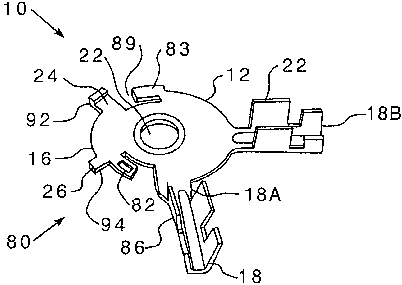
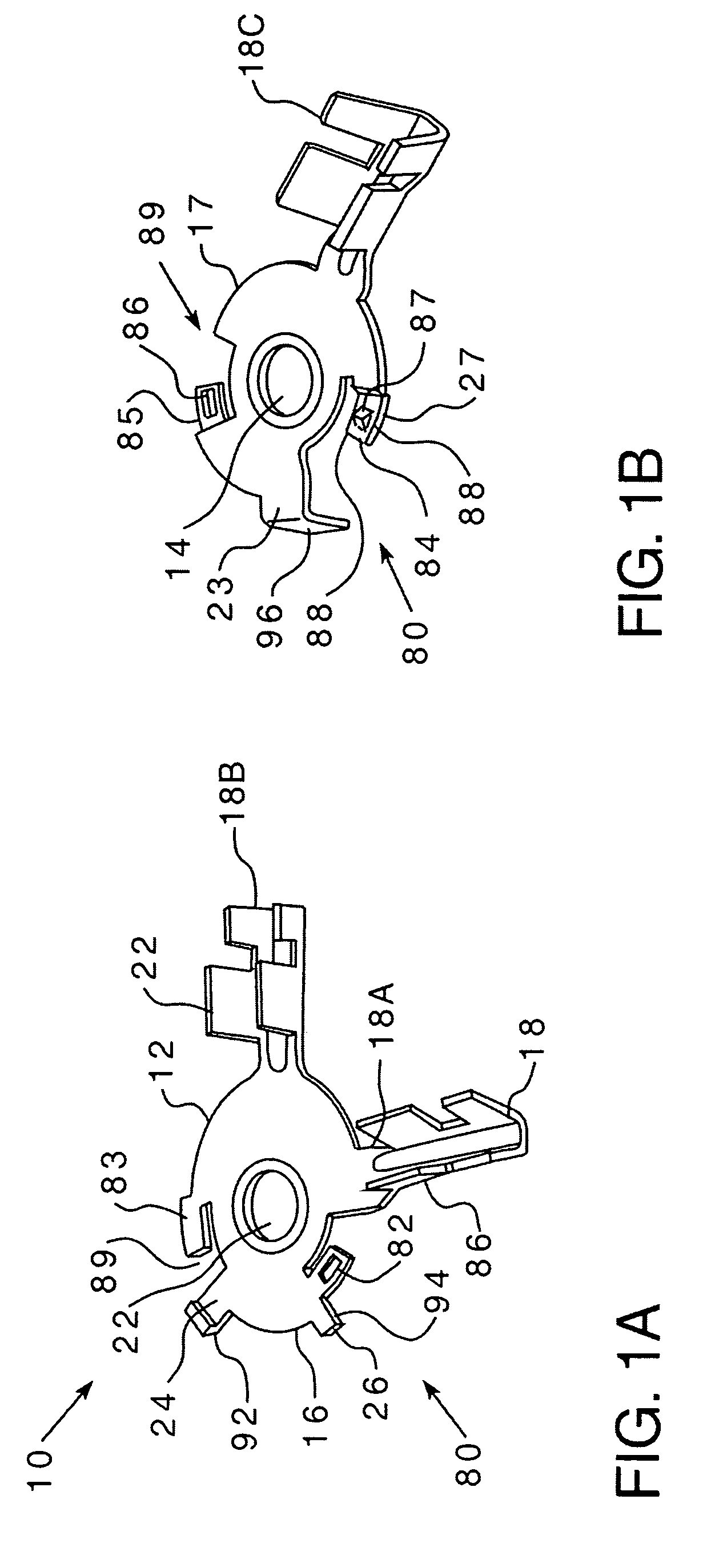
[0018]As shown in FIGS. 1A and 1B, a terminal ring assembly 10 includes a lower, first ring element 12 (FIG. 1A) and an upper, second ring element 14 (FIG. 1B). Both the first and second ring elements 12, 14 are, preferably, stamped from a flat sheet of conductive metal and shaped as follows. The terminal ring assembly first and second ring elements 12, 14 may be plated with a corrosion resistant material, such as tin. The first ring element 12 includes a generally circular, ring-like body 16, that is, a torus, and at least one radial arm, hereinafter a “grip”18, described more fully below. Preferably, and as discussed hereinafter, the first ring element 12 includes two grips 18A, 18B. The first ring element body 16 includes a central opening 22, a collar 24, having an outer diameter, disposed about the central opening...


PUM


Abstract

The present invention provides a terminal ring assembly structured for engagement to a conductor post. The terminal ring assembly of the present invention includes a first ring element and a second ring element, each having a circular body and at least one grip having crimpable barrels for engaging a wire in electrical connectivity. The first and second ring elements further include an interlocking device, in which the interlocking components of the first and second ring elements engage each other so that the first and second ring elements are locked together.

Description

FIELD OF THE INVENTION [0001]The present invention relates to an electric terminal, and, more specifically, to a ring terminal assembly formed from two ring elements and having multiple wire couplings.DESCRIPTION OF THE RELATED ART [0002]Ring terminals are typically used to couple a wire to a conductor. The ring terminal is made from an electrically conductive material and includes a flat ring-shaped body having a radial arm or “grip.” The grip is folded, or crimped, around the exposed end of an insulated electrical wire. The ring-shaped body is then disposed about a conductor post, such as a stud or a bolt. That is, the stud or bolt is passed through the ring-shaped body and the ring terminal is secured with a fastener. The stud or bolt is in electrical communication with an electrical system or circuit. Thus, following the installation of the ring terminal, the wire is also coupled to the electrical system or circuit. Such ring terminals are typically plated with a material such a...

Claims


Application Information

Patent Timeline
Patent Type & Authority Patents(United States)
IPC IPC(8): H01R11/11
CPCH01R11/12H01R11/32H01R4/185H01R13/03Y10S439/907
Inventor ZHAO, WEIPINGFARQUHAR, GEORGENOETHEN, GORDON
Owner AEES INC
Why Eureka
Try Eureka