
Electrosurgical working end for controlled energy delivery

a working end and controlled technology, applied in the field of hyperthermic treatment or ablation systems of targeted tissues, can solve the problems of insufficient control and localization of tissue volume elevated in temperature, lack of fluid content in tissue, and may never allow substantial deep active rf energy in the tissue volume around the electrode, so as to reduce the application of rf energy, prevent any substantial dehydration of tissue, and effectively apply energy to the tissue

Inactive Publication Date: 2006-10-24
ETHICON ENDO SURGERY INC
View PDF10 Cites 2127 Cited by
  • Summary
  • Abstract
  • Description
  • Claims
  • Application Information

AI Technical Summary

Benefits of technology

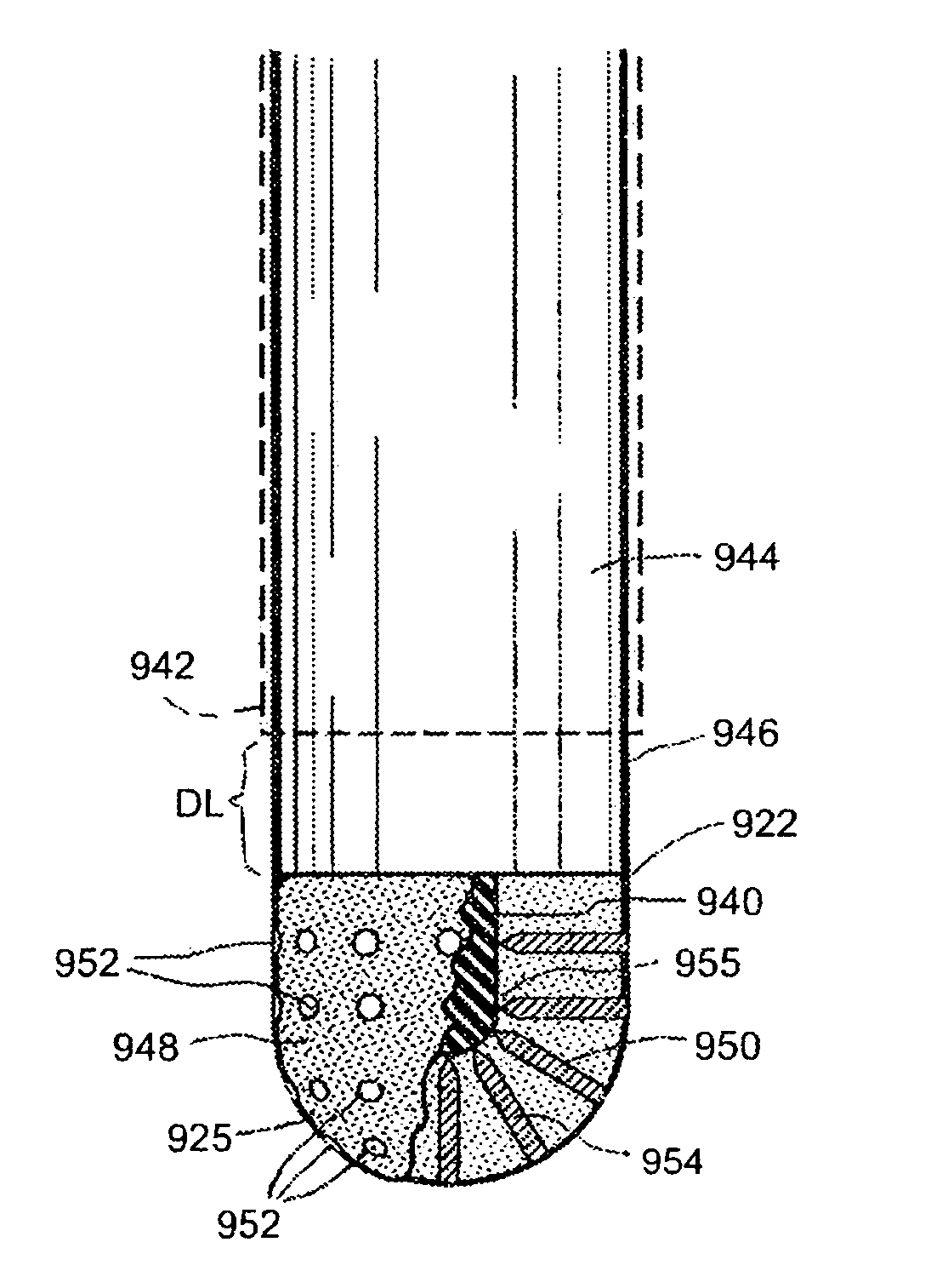
[0009]In general, the various embodiments of probes corresponding to the present invention all provide an Rf working end that is adapted to instantly and automatically modulate active Rf energy density in a targeted tissue without reliance of prior art “feedback” monitoring systems that measure impedance, temperature, voltage or a combination thereof. In an exemplary embodiment, a needle-type probe can be used for tumor ablation.
[0011]The working end of the invention utilizes a medial variable conductive matrix that has a selected switching range, for example a narrow 2–5° C. range, which approximates the target temperature of the thermally-mediated therapy. In operation, it can be understood that the engagement plane will apply active Rf energy to the engaged tissue until the medial conductive matrix is heated to the selected switching range. When the tissue temperature thus elevates the temperature of the medial PTC conductive layer to the switching range, Rf current flow from the core conductive electrode through to the engagement surface will be terminated due to the exponential increase in the resistance of medial conductive matrix. This instant and automatic reduction of Rf energy application can be relied on to prevent any substantial dehydration of tissue proximate to the probe's engagement plane. By thus maintaining an optimal level of moisture around the engagement plane, the working end can more effectively apply energy to the tissue—and provide a deeper thermal effect than would be possible with prior art Rf needles.
[0012]The working end of the probe corresponding to the invention further provides a suitable cross-section and mass for maintaining heat. Thus, when the medial variable conductive matrix is elevated in temperature to its switching range, the conductive matrix can effectively function as a resistive electrode to thereafter passively conduct thermal energy to the engaged tissue volume. Thus, in operation, the working end can automatically modulate the application of energy to tissue between active Rf heating and passive conductive heating of the targeted tissue to maintain the targeted temperature level.

Problems solved by technology

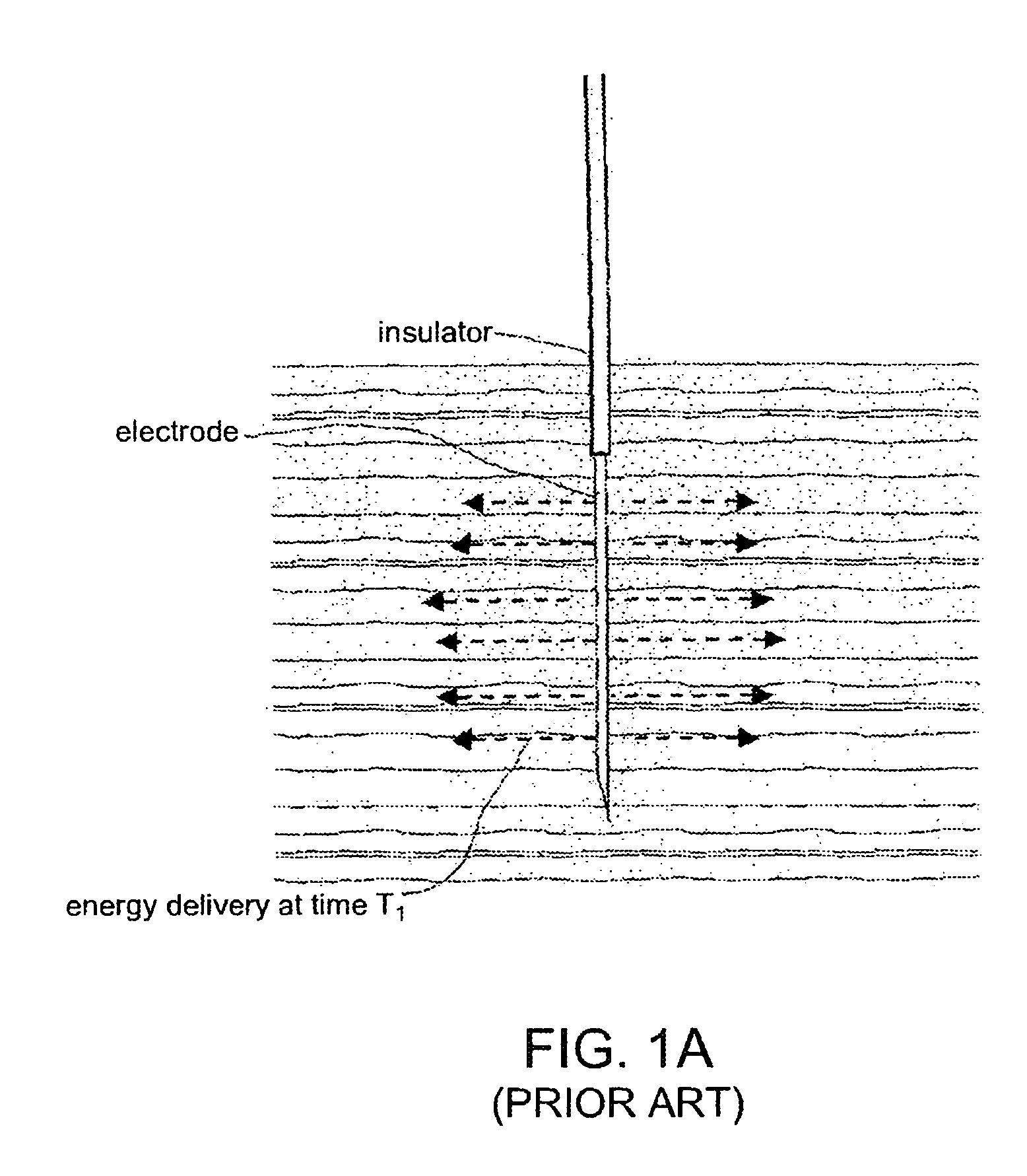
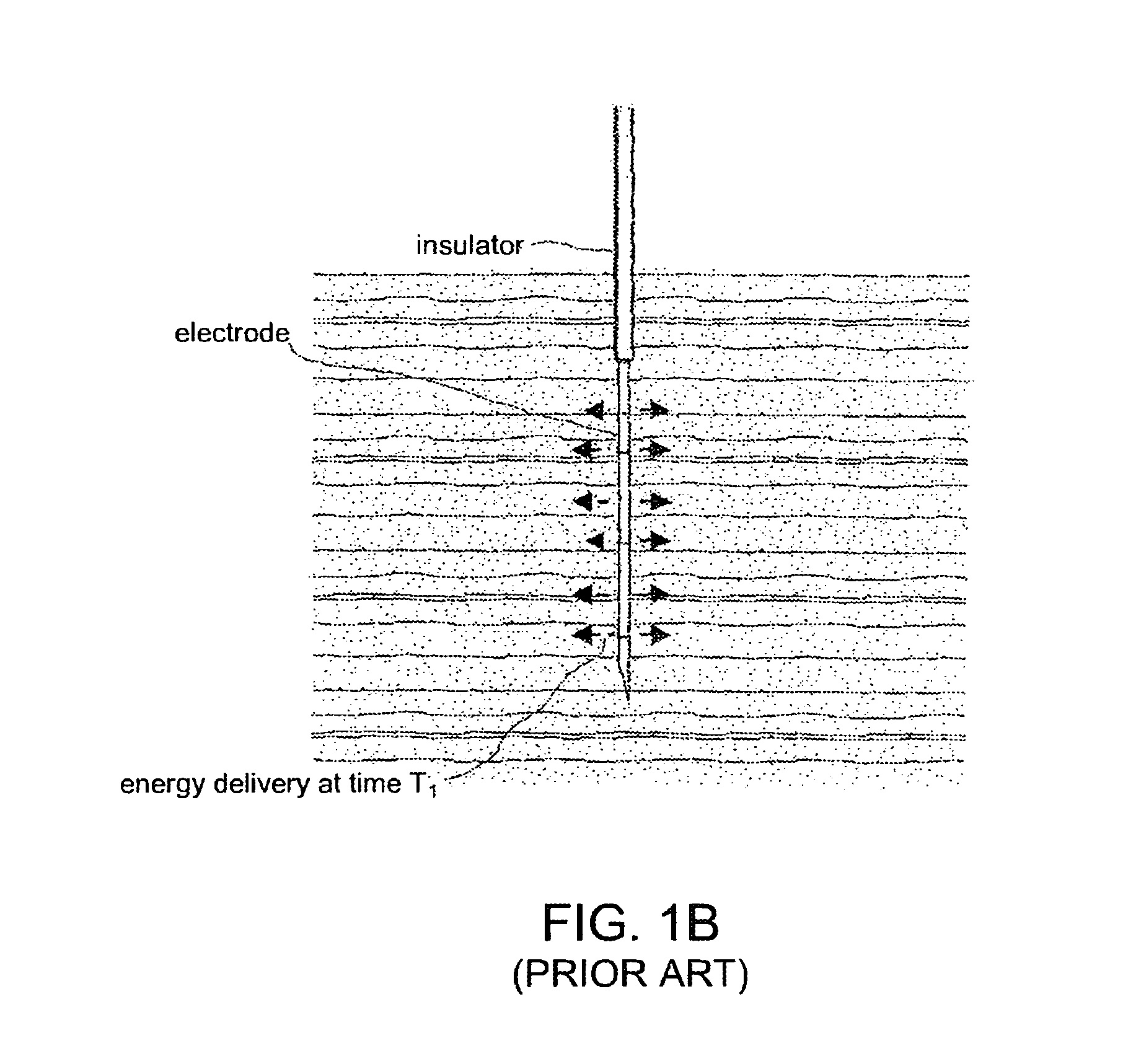
The principal problem related to the use of Rf electrode needles is that the tissue volume elevated in temperature is not adequately controlled and localized.
Thus, even if Rf power delivery to the tissue is modulated by a feedback mechanism, such as impedance monitoring, the lack of the fluid content in the tissue may never allow substantial deep active Rf energy in the tissue volume around the electrode.

Method used


Image

  • Electrosurgical working end for controlled energy delivery
  • Electrosurgical working end for controlled energy delivery
  • Electrosurgical working end for controlled energy delivery

Examples


Embodiment Construction

[0059]1. Type “A” probe for tumor ablation. An exemplary Type “A” probe 100 of the invention is illustrated in FIGS. 2 and 3 that is adapted for energy delivery to tissue, such as a targeted benign or malignant tumor. The probe 100 includes a proximal handle portion indicated at 106 and an introducer portion 110 that can be rigid or flexible in any suitable diameter. For example, the introducer portion 110 can be a diameter ranging from about 1 mm to 5 mm for use in percutaneous procedures or endoscopic procedures. The introducer portion extends from a proximal end 112a to a distal end 112b relative to longitudinal axis 115 and defines a bore 118 extending therethrough. The distal termination 112b of introducer 110 can be sharp for tissue penetration, as shown in FIGS. 2 and 3. In another embodiment, the introducer 110 can have a rounded distal end for introduction through a body passageway or lumen, such as an elongate catheter for endoluminal introduction. In another embodiment (n...


PUM


Abstract

An electrosurgical working end for automatic modulation of active Rf density in a targeted tissue volume. The working end of the probe of the present invention defines a tissue-engagement surface of an elastomeric material with conductive elements that extend therethrough. In one embodiment, the expansion of the elastomeric material can de-couple the conductive elements from an interior electrode based temperature to modulate current flow. In another embodiment, the elastomeric material can couple and de-couple the conductive elements from an interior electrode based on engagement pressure to modulate current flow

Description

CROSS-REFERENCES TO RELATED APPLICATIONS[0001]This application is a continuation of U.S. patent application Ser. No. 10 / 643,787 filed Aug. 19, 2003 now U.S. Pat. No. 7,070,597, which claimed the benefit of priority of U.S. Provisional Patent Application Ser. No. 60 / 404,703 filed Aug. 19, 2002, both of which are fully incorporated herein by reference. U.S. patent application Ser. No. 10 / 643,787 is also a Continuation-In-Part of U.S. patent applications: Ser. No. 10 / 982,482 filed Oct. 18, 2001 entitled Electrosurgical Working End for Controlled Energy Delivery and Ser. No. 10 / 032,867 filed Oct. 22, 2001 entitled Electrosurgical Jaw Structure for Controlled Energy Delivery, now U.S. Pat. No. 6,929,644, all of which are fully incorporated herein by reference.BACKGROUND OF THE INVENTION[0002]1. Field of the Invention[0003]This invention relates to systems and methods for delivering energy to tissue, and more particularly to systems for hyperthermic treatment or ablation of targeted tissu...

Claims


Application Information

Patent Timeline
Patent Type & Authority Patents(United States)
IPC IPC(8): A61B18/12
CPCA61B18/1477A61B2018/00083
Inventor TRUCKAI, CSABASHADDUCK, JOHN
Owner ETHICON ENDO SURGERY INC
Learn More