
Recessed floor box cover assembly

a technology for recessed floor boxes and assembly parts, which is applied in the direction of casings/cabinets/drawers, electrical apparatus, casings/cabinets/drawers details, etc., can solve the problems of tripping hazards, the cover cannot be closed or put back on the box, and the accumulation of water within the box can be detrimental to such components, so as to prevent access

Active Publication Date: 2006-10-24
THOMAS & BETTS INT INC
View PDF16 Cites 33 Cited by
  • Summary
  • Abstract
  • Description
  • Claims
  • Application Information

AI Technical Summary

Benefits of technology

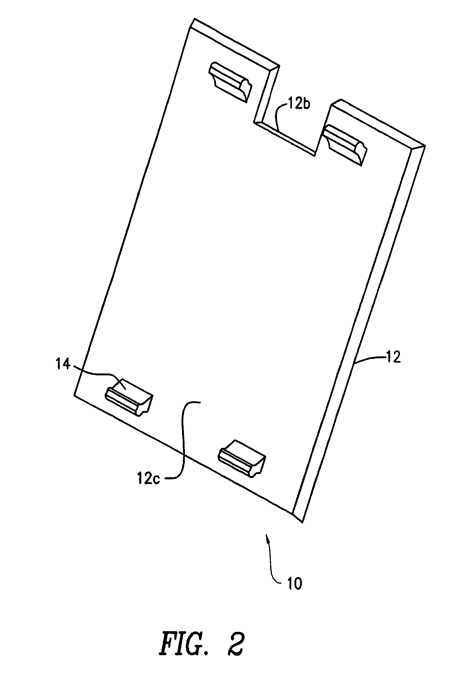
[0010]The present invention discloses a floor box cover assembly having a floor box housing including a bottom surface, an upstanding wall surrounding the surface terminating in an open face, and a tab projecting into an interior of the housing having a surface substantially flush with the open face. The assembly also includes a removable, repositionable cover including a notched-out portion adapted to align with the tab of the box housing such that when the cover is placed on top of the box housing, the notched out portion aligns with the tab to completely enclose the open face thereby preventing access therethrough. The cover is also repositionable for placement on top of the box housing such that the notched-out portion no longer aligns with the tab thereby providing an opening permitting wires to pass through.

Problems solved by technology

Undesirable accumulation of water within the box can be detrimental to such components.
Thus, the cover cannot be closed or put back on to the box when the wires or cables are connected into the interior of the box.
However, the door itself protrudes above the cover which can break off and may also create a tripping hazard.

Method used


Image

  • Recessed floor box cover assembly
  • Recessed floor box cover assembly
  • Recessed floor box cover assembly

Examples


Embodiment Construction

[0015]The present invention provides a recessed floor box cover assembly, more particularly a recessed floor box assembly which employs a lid or cover for covering the box while either in service or while not in service. The cover is removable and repositionable so as to selectively open or close an access opening into the box. The floor box cover assembly of the present invention is water resistant, thereby maintaining the covered electrical connections dry and free from any contamination.

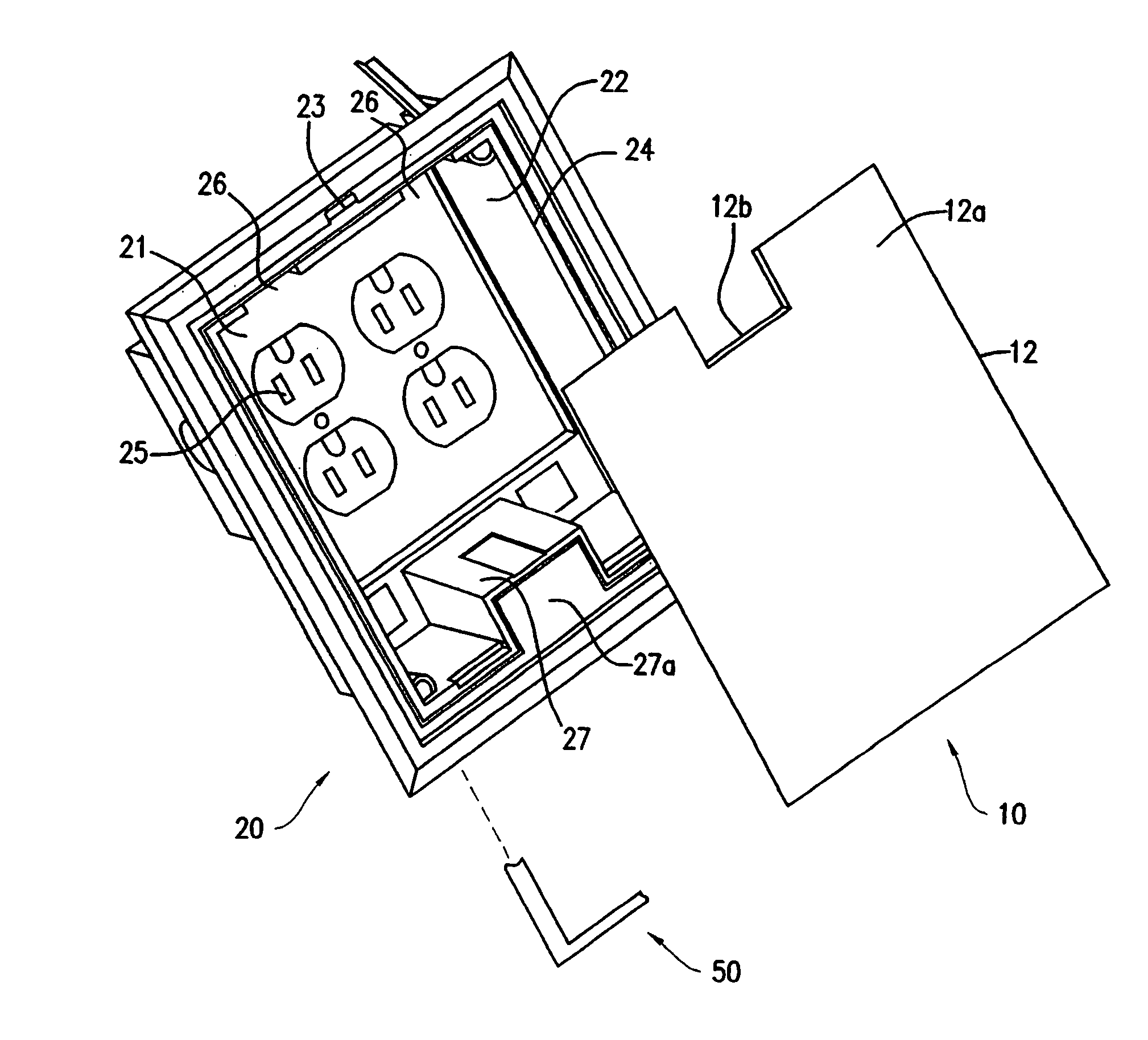
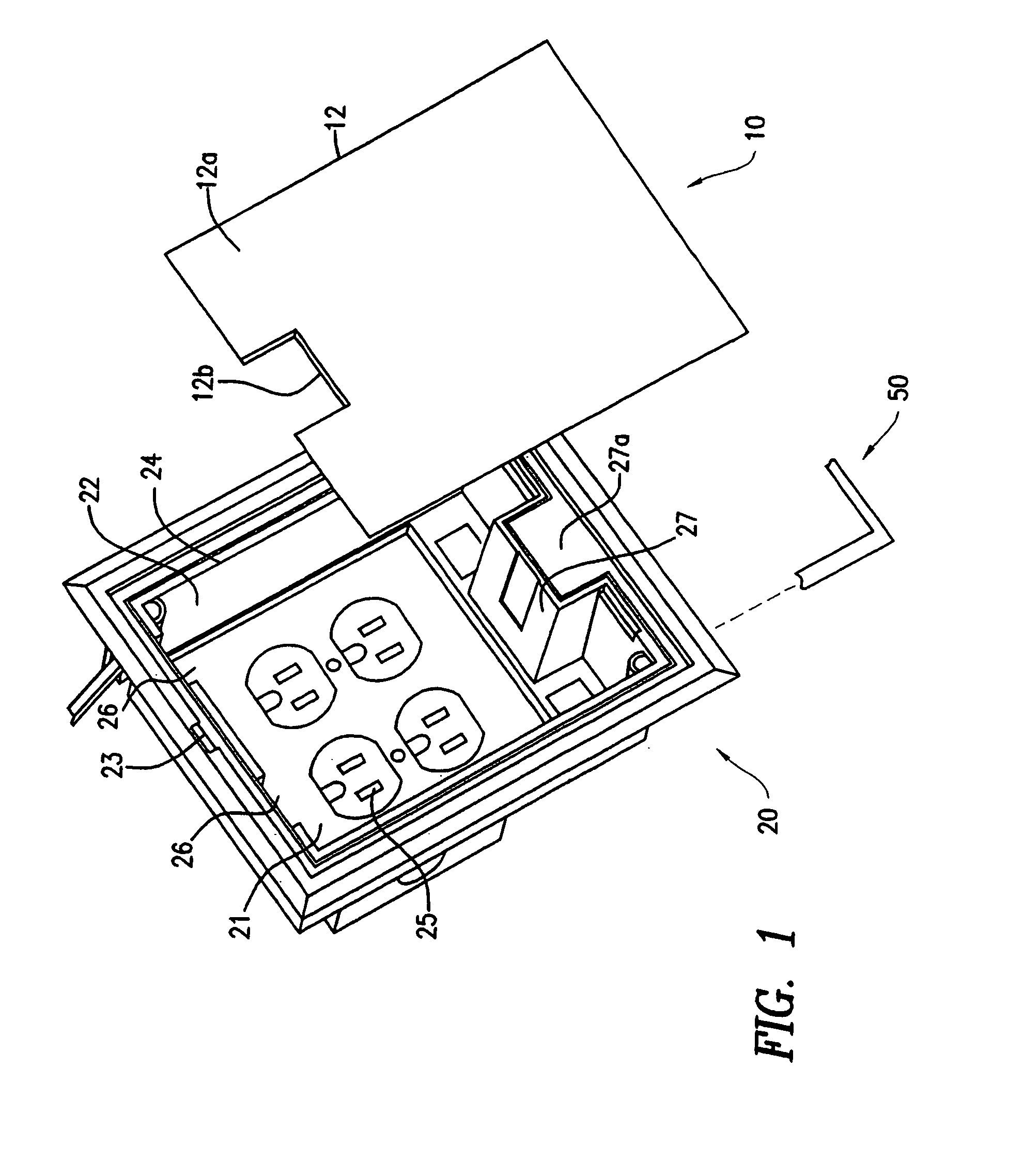
[0016]Referring to the FIG. 1, there is shown a perspective view of the floor box cover assembly 10 of the present invention. The floor box cover assembly 10 is used in combination with a floor box housing 20 to provide termination of power, data, and communication wires therethrough.

[0017]The embodiment of FIG. 1 shows a generally rectangular floor box housing 20 including a bottom flat surface 21 and an upstanding wall 22 surrounding all four sides of the surface 21 terminating in a generally re...


PUM


Abstract

The present invention provides a recessed floor box assembly including a cover and floor box housing designed to be adaptable to the cover. The cover is designed to be removable and repositionable for covering the open face of the box housing in either the closed or open positions. The cover can be selectively positioned to open or close an access opening into the box housing while still retaining a covering on the box housing.

Description

CROSS REFERENCE TO RELATED APPLICATION[0001]This application claims priority to U.S. Provisional Application No. 60 / 653,336, filed Feb. 16, 2005, which is incorporated herewith.FIELD OF THE INVENTION[0002]The present invention relates generally to recessed floor boxes which house power and communication wires or cables for termination. More specifically, the present invention relates to a recessed floor box assembly with a removable and reinsertable rotate snap cover for covering the box while either in service or while not in service.BACKGROUND OF THE INVENTION[0003]It is well known to run electrical wires and telecommunications wires underneath the surface of a floor. These cables and electrical systems may be placed under the floor surface so as to be more efficient in supplying power and data / telecommunication signals in commercial buildings. The electrical cables or wires beneath the floor may be accessed through a hole in the surface of the floor. In order to provide convenien...

Claims


Application Information

Patent Timeline
Patent Type & Authority Patents(United States)
IPC IPC(8): H02G3/14
CPCH02G3/14H02G3/185
Inventor DINH, CONG THANHWARREN, KEVIN
Owner THOMAS & BETTS INT INC
Learn More