
Connector for affixing cables within junction boxes

a technology of connecting cables and junction boxes, applied in the direction of connection, electrical apparatus, coupling device connection, etc., can solve the problems of increasing the number of tools, increasing labor and time, and increasing the difficulty of operation, and achieve the effect of increasing rigidity

Active Publication Date: 2006-10-24
ATKORE STEEL COMPONENTS INC
View PDF40 Cites 28 Cited by
  • Summary
  • Abstract
  • Description
  • Claims
  • Application Information

AI Technical Summary

Benefits of technology

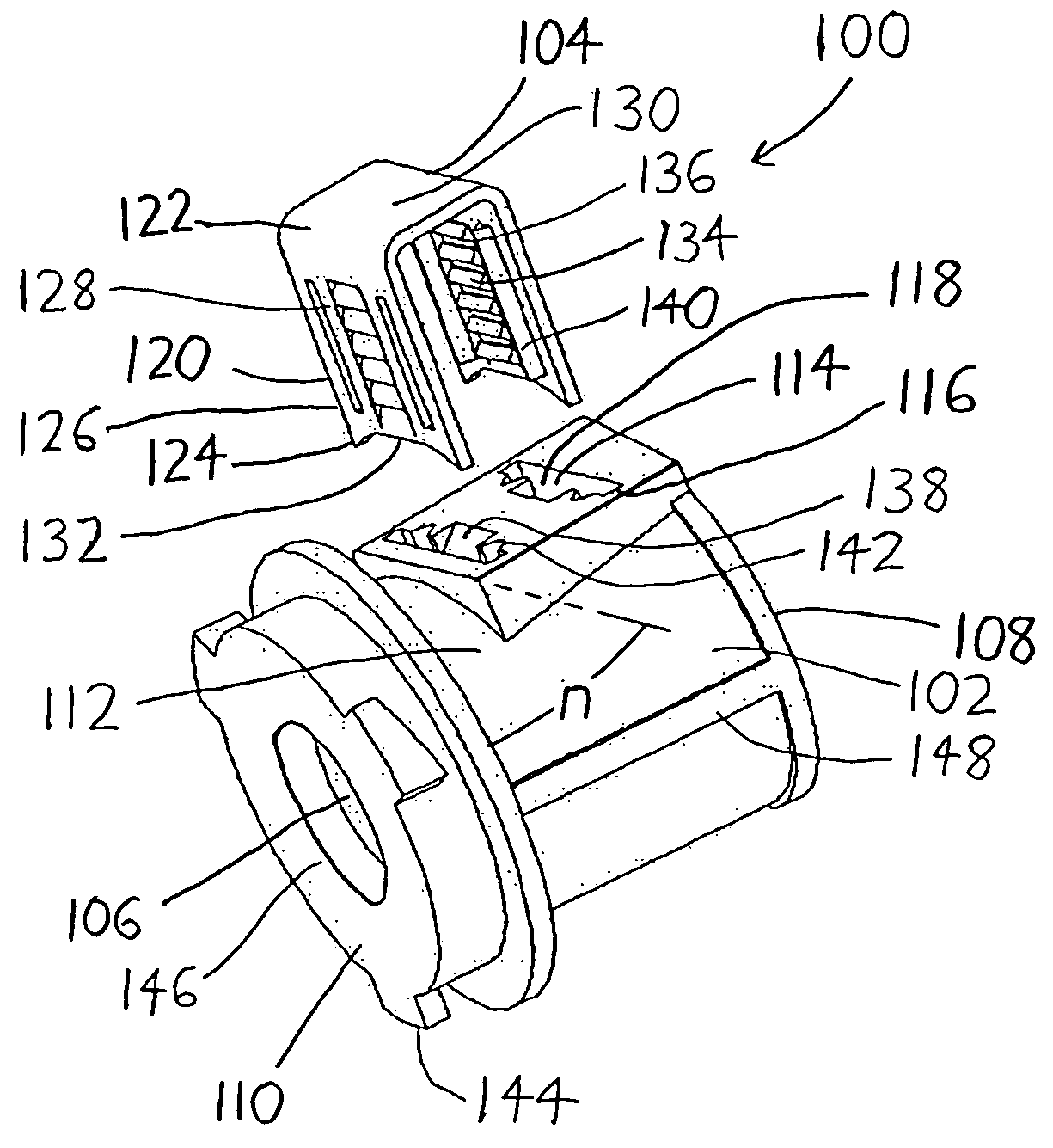
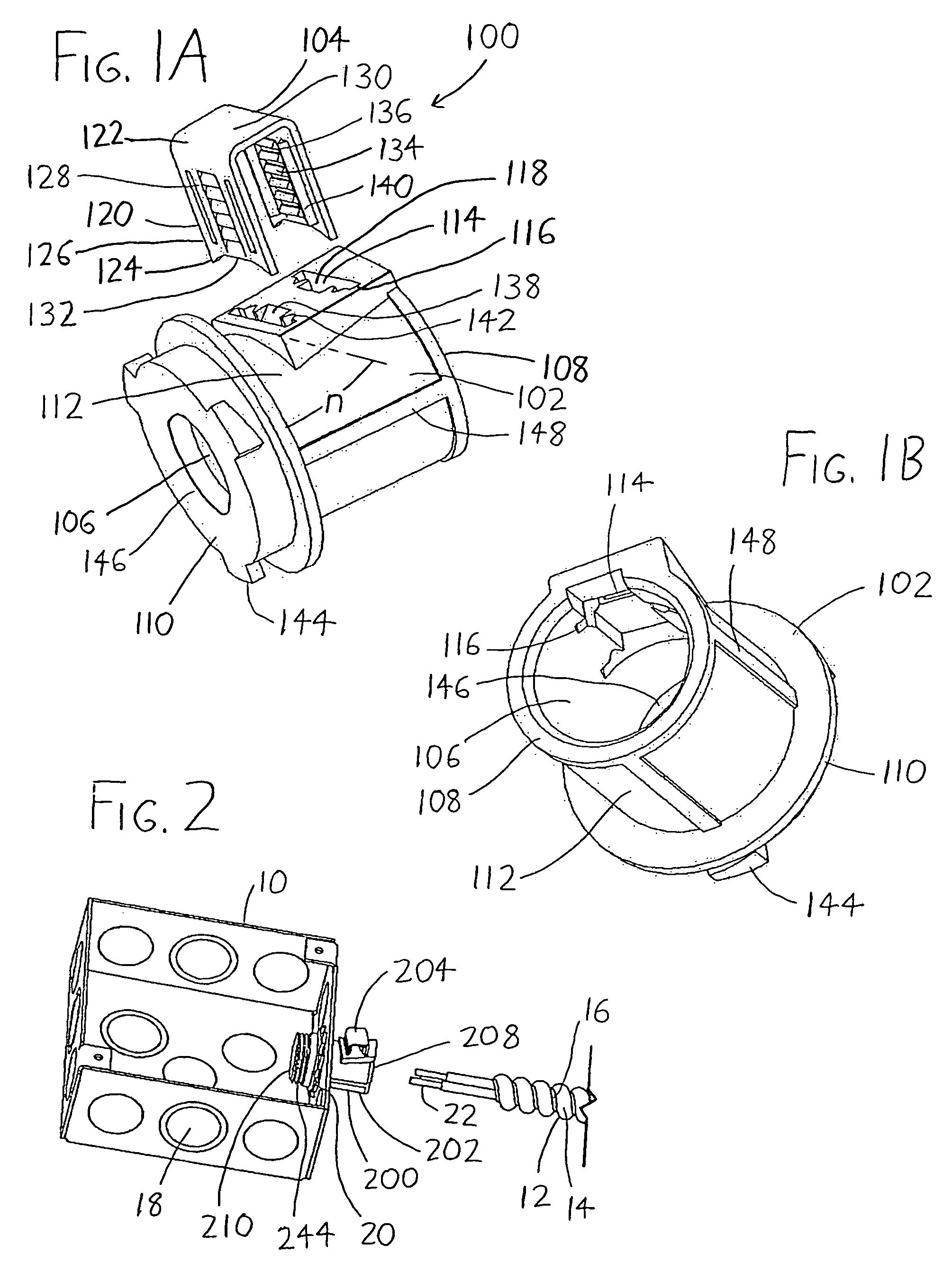
[0009]In the preferred form of the engagement member 104 shown in FIGS. 1A and 2, the engagement member 104 has a staple-like U-shaped configuration wherein the engagement legs 120 are substantially planar bar-shaped members which are somewhat flexible with respect to the bridge 130, better allowing them to be urged into the slots 114 despite any casting imperfections that may be present in the body 102 (since the body 102 is preferably formed of cast metal, though it could be formed of plastic or other substances). To provide additional rigidity to the engagement legs 120 so that they do not bow outwardly when the bridge 130 is pressed, the engagement legs 120 may include one or more raised ribs 140 spaced from the teeth 134, and which extend between the insertion ends 124 and the driving ends 122 of the engagement legs 120 (with the preferred engagement member 104 each including a pair of ribs 140 on the engagement leg faces 128 on opposing sides of the teeth 134). The slots 114 may then bear notches 142 extending along their slot depths between the outer body surface 112 and the internal passage 106, with the notches 142 being sized and aligned to complementary receive the ribs 140 when the engagement legs 120 are inserted within their slots 114.

Problems solved by technology

These arrangements can be inconvenient because they require the use of tools to connect the cable to the junction box, and in some instances the connection may need to be performed within tight confines (e.g., within a small hole in a wall), making the operation difficult to perform.
Additionally, the need to use tools increases the time needed to install cables within junction boxes, since the steps of inserting and fixing the connector within the junction box, inserting the cable within the connector, obtaining and using a tool to fix the cable within the connector, etc. often require that an electrician or other installer pick items up, set them down, switch them from hand to hand, etc., which can rapidly grow tedious and annoying.

Method used


Image

  • Connector for affixing cables within junction boxes
  • Connector for affixing cables within junction boxes

Examples


Embodiment Construction

[0015]To expand on the discussion given in the Summary above, the cable connector is intended to be installed within a junction box 10 (see FIG. 2) by attaching it to a junction box entry 18 (with the body 202 of the exemplary cable connector 200 being shown attached at the second body end 210), and to receive a cable 12 within the internal passage of the cable connector for attachment therein. These steps are preferably performable with a single hand, with no or few tools, and with as few steps as possible to achieve fixture of the cable connector to both the junction box and the cable. The cable connectors 100 and 200 shown in the drawings attain these goals, but it should be understood that the cable connector may assume a wide variety of forms other than those illustrated in the drawings. A number of different exemplary modifications will now be described, using the cable connector 100 of FIGS. 1A–1B as a point of reference.

[0016]Initially, while the exemplary cable connector 10...


PUM


Abstract

A connector for affixing cables (e.g., of the type having wires bundled within a corrugated cover) within an electrical or other junction box has a body with a first end into which the cable cover (and the wires therein) may be inserted, and a second end configured to affix to the entry of a junction box, and which is configured to allow the wires of the cable to leave the connector and extend into the junction box. The connector has an engagement member thereon with one or more engagement legs which extend into the body of the connector, and into the internal passage of the connector body into which the cable is fit, to engage the cable cover and fix the cable to the connector body.

Description

FIELD OF THE INVENTION[0001]This document concerns an invention relating generally to electrical wiring components, and more specifically to connectors for securing electrical cables to electrical junction boxes.BACKGROUND OF THE INVENTION[0002]In the electrical trade, junction boxes—small boxes / compartments made of plastic or other materials, with at least one open wall and having entries / apertures defined in other walls—are often installed in buildings at points where electrical wires are to be connected to components such as sockets, switches, outlets, and / or other wires. A junction box is installed at the point where the connection is desired, usually within the building wall or ceiling, by nailing or screwing the junction box to a stud within the wall or ceiling. Multi-wire cable is brought to the junction box and extended through an entry point in a junction box wall to enter the junction box interior. The cable is usually sheathed within a corrugated cover, often formed of a ...

Claims


Application Information

Patent Timeline
IPC IPC(8): H02G3/18
CPCH01R13/5812H02G3/0666
Inventor SHEMTOV, SAMI
Owner ATKORE STEEL COMPONENTS INC
Learn More