
Method and system for processing a non-linear two dimensional spatial transformation

a two-dimensional spatial transformation and processing method technology, applied in image enhancement, instruments, computing, etc., can solve the problems of significant memory requirements, limitation of the complexity of the transformation, and inacceptable video processing of image artifacts created using this simplified filtering

Active Publication Date: 2006-10-24
GEO SEMICONDUCTOR INC
View PDF17 Cites 26 Cited by
  • Summary
  • Abstract
  • Description
  • Claims
  • Application Information

AI Technical Summary

Benefits of technology

[0013](e) comparing an evaluation of said first and second 1D geometrical transformations at each pixel with an evaluation of the analytical in

Problems solved by technology

These compromises result in limitations on the complexity of the transformation and / or introduce results that do not match the transformation exactly.
Using piecewise linear representations for the geometric distortions can significantly increase memory requirements.
The image artifacts created using this simplified filtering are unacceptable for video processing.
However, a pixel-by-pixel representation requires a large amount of data storage and does not allow for a simple method of performing manipulations of the geometric transformation (example rotation, scaling translation of an image in addition to the geometric transformation).
Methods that use mathematical models of the spatial transformation and allow the user to adjust the parameters of the model are often limited to affine and perspective warps.
As has already been discussed, affine or perspective warps cannot adequately model distortions required for optical systems.

Method used


Image

  • Method and system for processing a non-linear two dimensional spatial transformation
  • Method and system for processing a non-linear two dimensional spatial transformation
  • Method and system for processing a non-linear two dimensional spatial transformation

Examples


Embodiment Construction

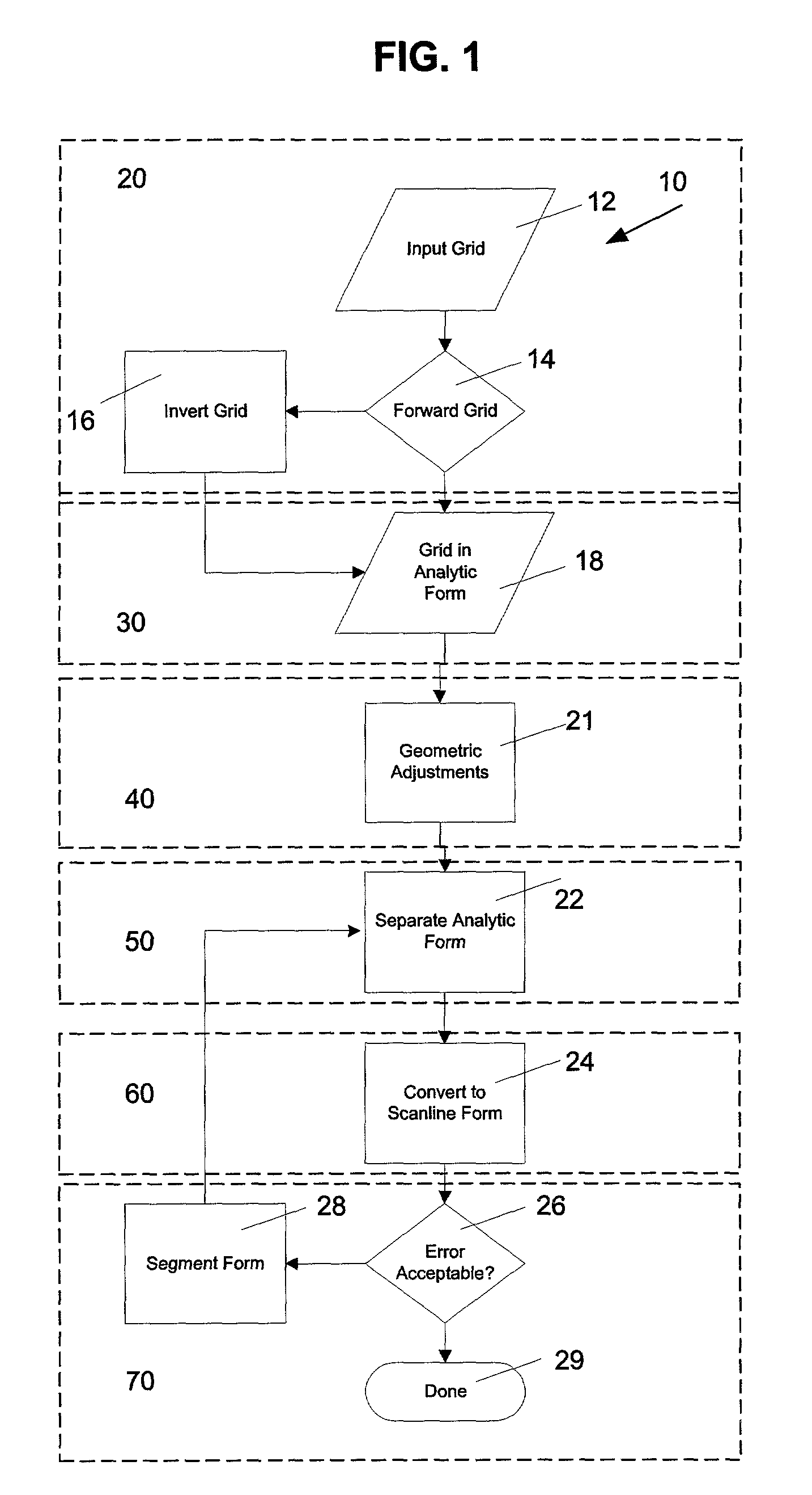
[0045]FIG. 1 is a detailed flowchart diagram that illustrates the image transformation method 10 used to achieve transformation of an input image to an output image according to a non-linear 2D spatial transformation, according to the present invention. The six main stages of the method are illustrated in FIG. 1, namely a inverse transformation stage 20, an analytical stage 30, a geometric transformation stage 40, a separation stage 50, a conversion stage 60, and a error check stage 70. These stages will be discussed in further detail throughout the following disclosure.

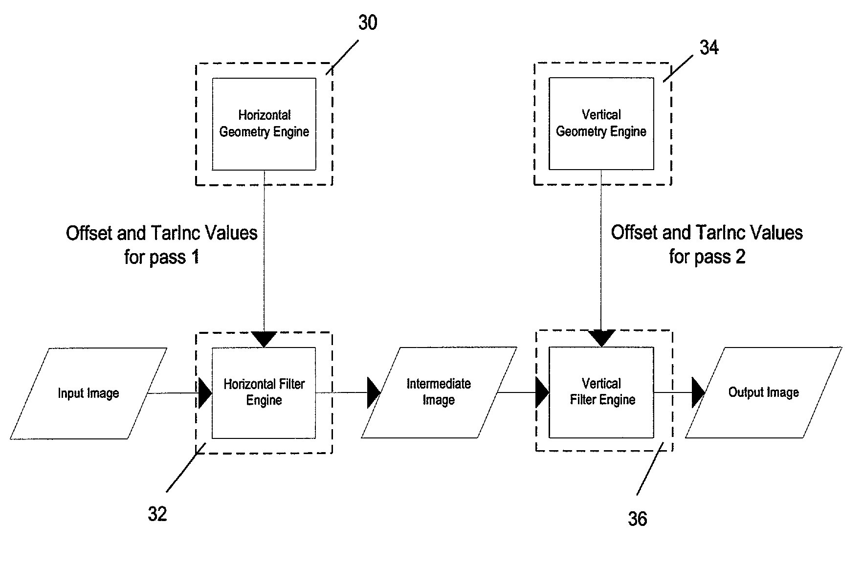
[0046]The image transformation method 10 of the present invention provides a separable two-pass transform for processing an image warp in separate horizontal and vertical passes, allowing the 2D spatial transform to be defined as two 1D processes. Accordingly, any system where a 2D spatial transformation needs to be applied can make use of image transformation method 10. Image transformation method 10 can be used in ...


PUM


Abstract

An image transformation method for translating a non-linear 2D geometrical transformation into two separable 1D geometrical transformations first determines the inverse of the 2D geometrical transformation to form an inverse 2D geometrical transformation. Then the method converts the inverse 2D geometrical transformation into an analytical inverted 2D geometrical transformation and separates the analytical inverse 2D geometrical transformation into first and second 1D geometrical transformations. The method then represents said inverse 2D geometrical transformation and first and second 1D geometrical transformations as tensor spline surfaces and then compares an evaluation of said first and second 1D geometrical transformations at each pixel with an evaluation of the analytical inverse 2D geometrical transformation at each pixel. If the error evaluation does not meet a predetermined level of performance then the separation and transformation steps are repeated. Since the method involves one-dimensional spatial transform processing it results in reduced calculations, efficient memory access, and ability to process data in a real-time environment. In-addition, since the method provides a compact representation of the spatial transforms, it can be scaled for a particular level of precision.

Description

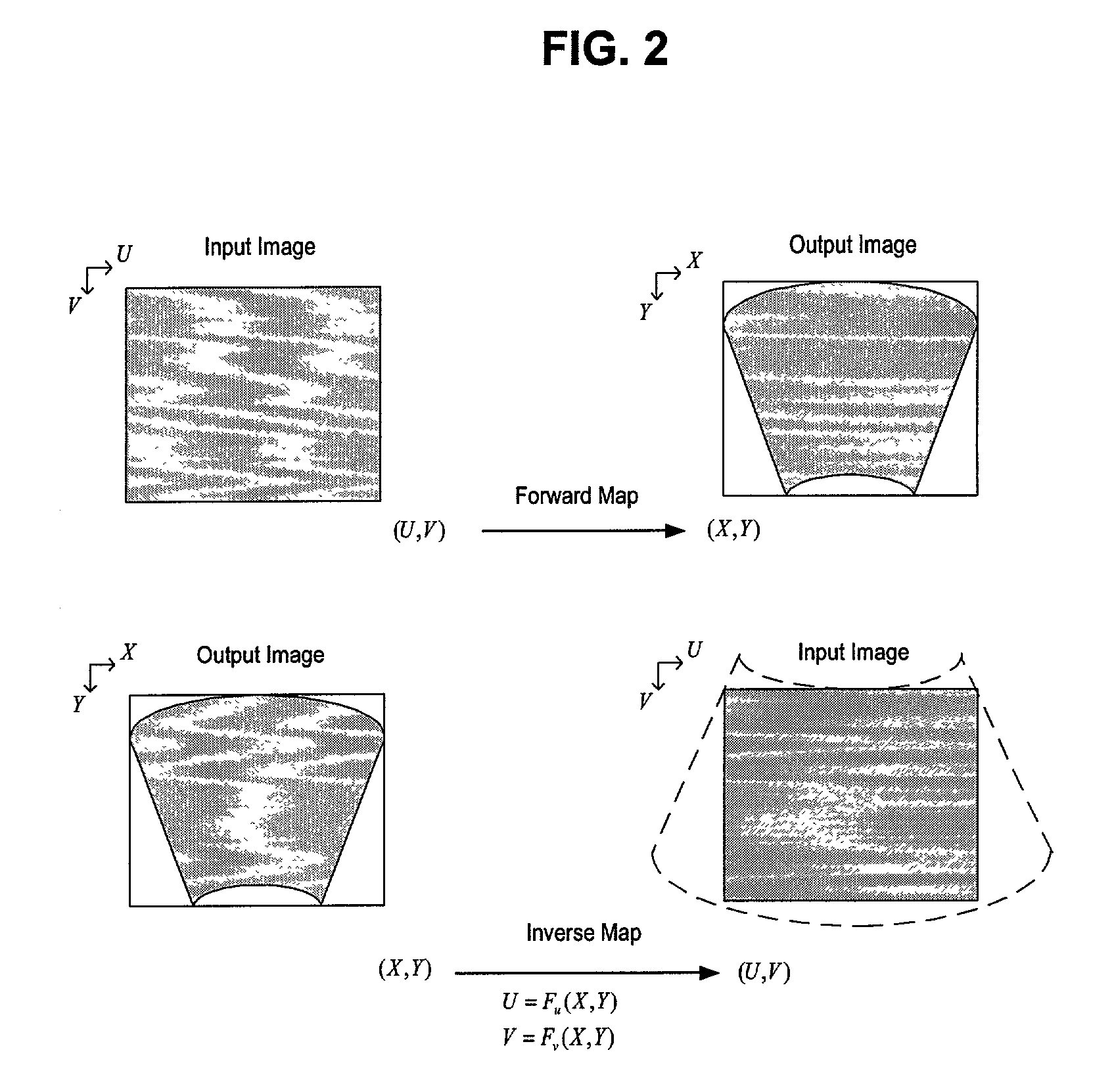
[0001]This regular application claims priority from provisional U.S. Application No. 60 / 297,240 filed Jun. 12, 2001.FIELD OF THE INVENTION[0002]This invention relates to the field of video image processing and more particularly to the processing of a non-linear 2D spatial transformation.BACKGROUND OF THE INVENTION[0003]Geometric or spatial transformations are operations that redefine spatial relationships between points in an image. Generally, a spatial transformation is defined as a mapping function that establishes a spatial correspondence between all points in the input and output images. Given a spatial transformation, each point in the output assumes the value of its corresponding point in the input image. Common applications for applying a geometric transformation include image distortion correction, compensation of geometrically distorted image projected on non-flat or perpendicular surfaces, and compensation of optical distortions.[0004]Geometric transformation algorithms us...

Claims


Application Information

Patent Timeline
IPC IPC(8): G09G5/00G06T5/00
CPCG06T5/006G06T5/80
Inventor JASA, TOMISLAVBASSI, ZORAWAR S.LEE, LOUIE
Owner GEO SEMICONDUCTOR INC
Learn More