
Method and apparatus for scalable video encoding and decoding

a video encoding and decoding technology, applied in the field of video compression, can solve the problems of voluminous multimedia data, poor compression performance of schemes, and insatiable consumers with existing text-based communication schemes

Inactive Publication Date: 2005-06-02
SAMSUNG ELECTRONICS CO LTD
View PDF8 Cites 46 Cited by
  • Summary
  • Abstract
  • Description
  • Claims
  • Application Information

AI Technical Summary

Benefits of technology

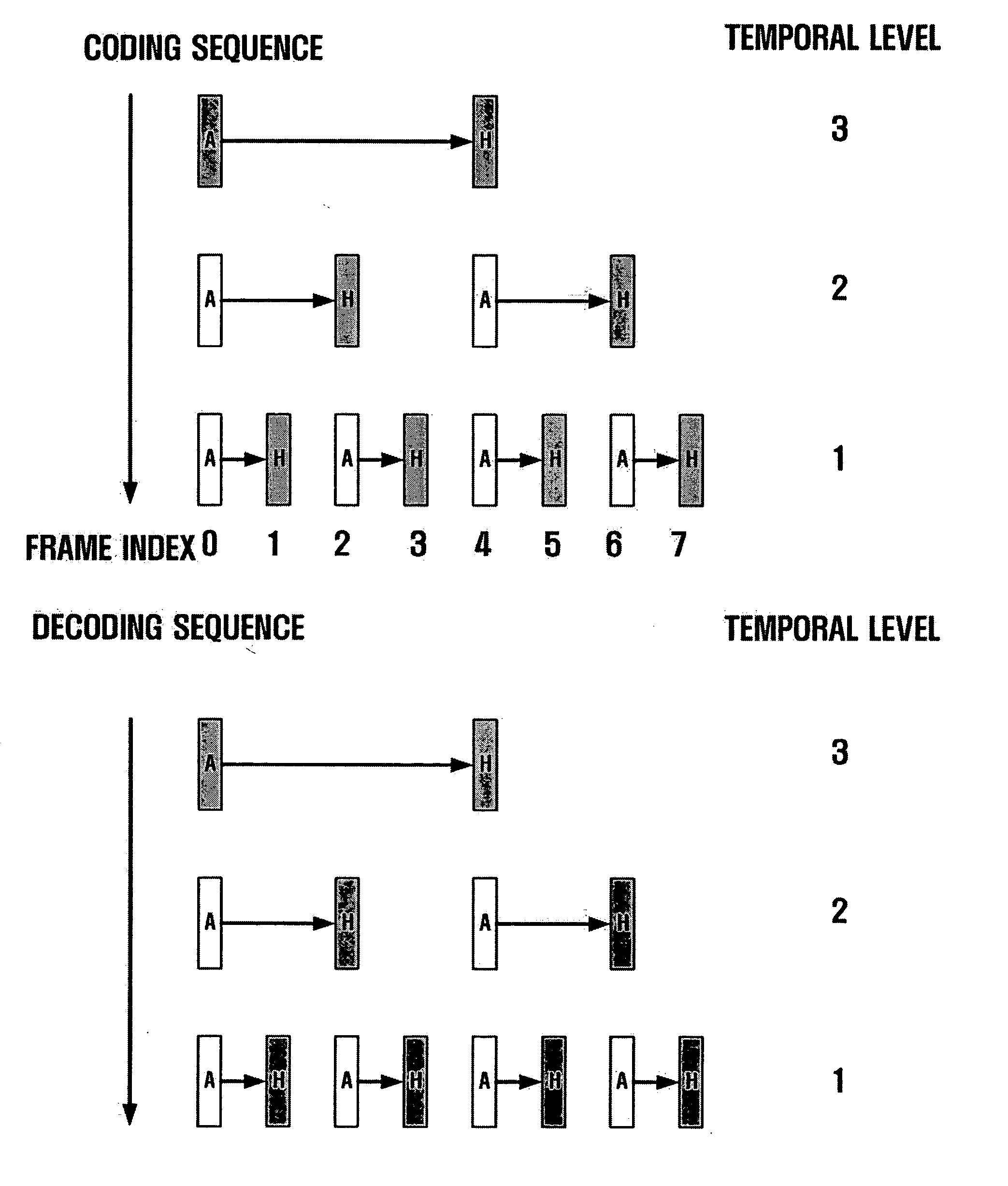
[0017] Accordingly, the present invention has been conceived to satisfy the need described above. An aspect of the present invention is to provide a video coding and decoding method and apparatus wherein an encoder-side has temporal scalability.
[0019] With respect to the frames at the same temporal level in step (a), the temporal redundancy thereof may be eliminated from the frame having the least index (the frame having the soonest temporality) to the frame having the highest index (the frame having the latest temporality).

Problems solved by technology

However, consumers have not been satisfied with existing text-based communication schemes.
Multimedia data is usually voluminous such that it requires a storage medium having large capacity.
These schemes have good performance in compression but they have little flexibility for a true scalable bit-stream because main algorithms of the schemes employ recursive approaches.
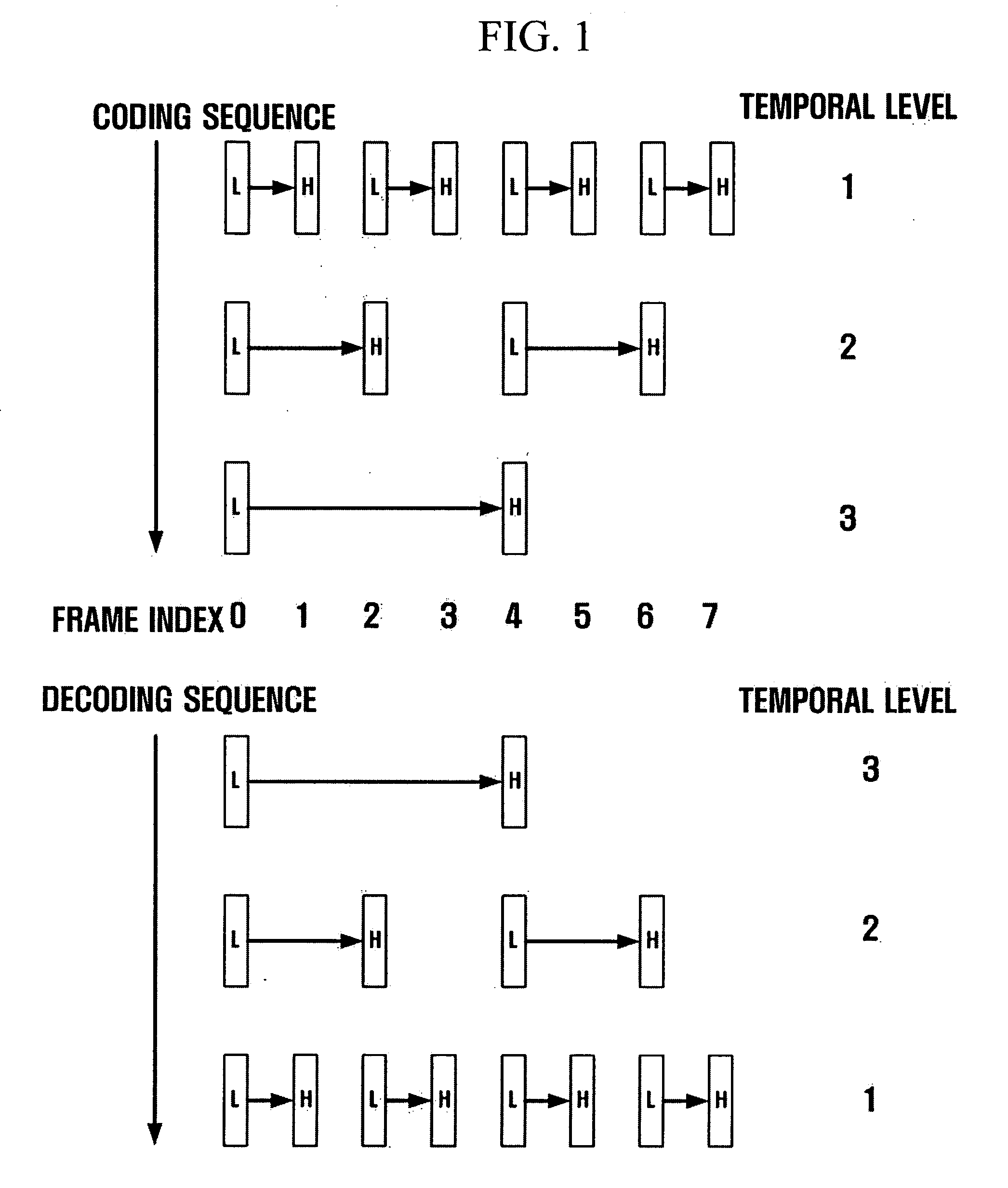
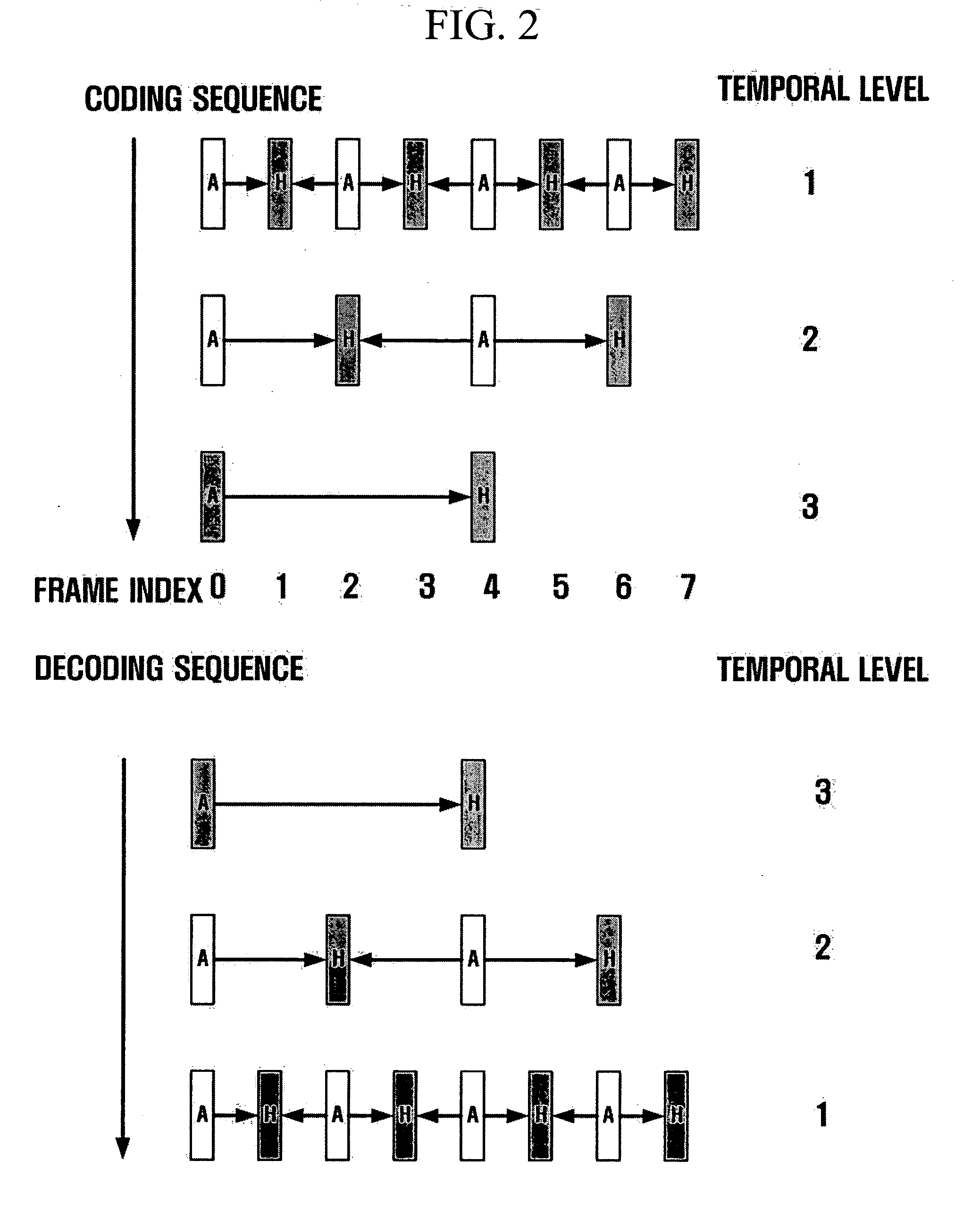
The video coding employing the original MCTF scheme has temporally flexible scalability, but it may have some disadvantages such as poor performance in uni-directional motion estimation and low quality at low temporal rates and so on.
However, when a video is compressed by use of a conventional MCTF (or UMCTF)-based scalable video coding algorithm, the encoder-side has no flexible temporal scalability.
The frame at the highest temporal level can only be obtained after passing through the whole encoding process in the conventional schemes, and thus, the encoder-side cannot suspend temporal filtering because of operation capability or other reasons.

Method used


Image

  • Method and apparatus for scalable video encoding and decoding
  • Method and apparatus for scalable video encoding and decoding
  • Method and apparatus for scalable video encoding and decoding

Examples


Embodiment Construction

[0048] Hereinafter, exemplary embodiments of the present invention will be described in detail with reference to the accompanying drawings.

[0049] A scalable video coding algorithm compresses frames on a GOP (Group of Picture) basis. The size of a GOP (the number of frames constituting a GOP) may be determined differently depending upon a coding algorithm but is preferably determined to be 2n (n is a natural number). The GOP is assumed to have 8 frames in the exemplary embodiments of the present invention to be described later; however, this is merely by way of example. In this regard, even though the GOP size varies, this should be construed to fall under the protected scope granted to the present invention as far as it implies the technical idea of the present invention.

[0050]FIG. 3 illustrates temporal decompositions in scalable video coding and decoding according to an exemplary embodiment of the present invention.

[0051] Referring to FIG. 3, both temporal decompositions (that ...


PUM


Abstract

Disclosed is a scalable video coding algorithm. A method for video coding includes temporally filtering frames in the same sequence to a decoding sequence thereof to remove temporal redundancy, obtaining and quantizing transformation coefficients from frames whose temporal redundancy is removed, and generating bitstreams. A video encoder comprises a temporal transformation unit, a spatial transformation unit, a quantization unit and a bitstream generation unit to perform the method. A method for video decoding is basically reverse in sequence to the video coding. A video decoder extracts information necessary for video decoding by interpreting the received bitstream and decoding it. Thus, video streams may be generated by allowing a decoder to decode the generated bitstreams, while maintaining the temporal scalability on an encoder-side.

Description

CROSS-REFERENCE TO RELATED APPLICATIONS [0001] This application is based on and claims priorities from Korean Patent Application No. 10-2004-0003983 filed on Jan. 19, 2004 in the Korean Intellectual Property Office and U.S. Provisional Patent Application Nos. 60 / 525,827 and 60 / 532,179 filed on Dec. 1 and 24, 2003, respectively, in the United States Patent and Trademark Office, the disclosures of which are incorporated herein in their entireties by reference.BACKGROUND OF THE INVENTION [0002] 1. Field of the Invention [0003] The present invention relates generally to video compression, and more particularly, to a video coding algorithm in which the temporal filtering sequence in an encoding process is inversed in a decoding process. [0004] 2. Description of the Related Art [0005] Development of information communication technologies including the Internet has led to an increase in video communication, as well as text and sound communication. However, consumers have not been satisfied...

Claims


Application Information

Patent Timeline
IPC IPC(8): H04N7/12H04N7/24
CPCH04N19/13H04N19/63H04N19/615H04N19/31H04N19/85H04N19/61H04N19/30H04N19/177
Inventor HAN, WOO-JIN
Owner SAMSUNG ELECTRONICS CO LTD
Learn More