
Label switched communication network, a method of conditioning the network and a method of data transmission

a technology of label switching and communication network, applied in the field of label switching communication network, can solve the problems of time required to complete restoration for large number of lsps, difficulty in ensuring the continuity of the network, so as to reduce the time of restoration

Inactive Publication Date: 2006-10-24
WSOU INVESTMENTS LLC +1
View PDF14 Cites 97 Cited by
  • Summary
  • Abstract
  • Description
  • Claims
  • Application Information

AI Technical Summary

Benefits of technology

[0009]In this arrangement, the first switching router is adapted or configured, when enabled by the first enabling means to route predetermined data for transmission to the second switching router along the first communication path, and is adapted or configured when enabled by the second enabling means to route the predetermined data along the second communication path. In one embodiment, at least one of the first and second enabling means may comprise an instruction which adapts or configures the first switching router to perform the specified function. The instruction may be stored for example in the first switching router and activated when required, and disabled when not required. When the first switching router is enabled by the second enabling means, data which is output from the first switching router or node element onto the second communication path, which may be used for protection or restoration, includes both a flow label which is readable by the second switching router, and corresponds to an instruction associated with the data and held at the second switching router, and a path identification label which identifies the path between the first and second switching routers along which the data is to be transmitted. Advantageously, the flow label output with the specified data onto the secondary path can be the same as that for routing with the specified data on the primary path, and since this label is not path dependent, the first switching router is not required to change or transform this label when the specified data is output onto the secondary path, for example, on restoration of data transmission due to a fault on the primary path. Thus, whereas in the prior art schemes, the router responsible for switching data onto the protection path is required to store a second set of labels associated with each secondary LSP and to change to the secondary LSP labels on restoration, the present scheme employs the same instruction label for both paths, avoiding the need for storing a second set of LSP labels and for processing the table during path restoration.
[0011]The second communication path label which is output with data from the first switching router onto the second communication path operates as a label in defining the secondary label switched path between the first and second switching routers. The labelling system for the secondary path may be established during path set-up which, if used for protection, is set up prior to the occurrence of a fault or failure in the primary path or, for restoration, after the occurrence of a fault on the primary path. In order to output data intended for transmission to the second switching router onto the secondary path, the addition of the secondary path LSP label is simply required, whereas the flow label for the specified data remains unchanged. Thus, regardless of the number of different flow labels associated with data for transmission to the second switching router, only a single operation of adding a single, common label to all data is required. Therefore, to protect or restore data transmission between two nodes, the present communication network only requires a single LSP to be established on secondary path rather than an LSP for each flow label or data flow, providing a significant reduction in restoration time and a fully scalable protection or restoration scheme.

Problems solved by technology

One particular drawback of this known system is the time required to set up the secondary LSPs, which increases with the number of LSPs carried on the primary path, each of which requires a secondary LSP to be dialled over the secondary path.
This problem may become particularly severe when invoking a path restoration scheme which may involve establishing (or dialling) many, for example a thousand or more secondary LSPs when a failure occurs on the primary path.
Although such a restoration scheme may be practical for small numbers of LSPs, the time required to complete restoration for large numbers of LSPs may be unacceptable, and therefore such a scheme is not particularly scalable.
However, none of these proposed approaches addresses the scalability concerns mentioned above.

Method used


Image

  • Label switched communication network, a method of conditioning the network and a method of data transmission
  • Label switched communication network, a method of conditioning the network and a method of data transmission
  • Label switched communication network, a method of conditioning the network and a method of data transmission

Examples


Embodiment Construction

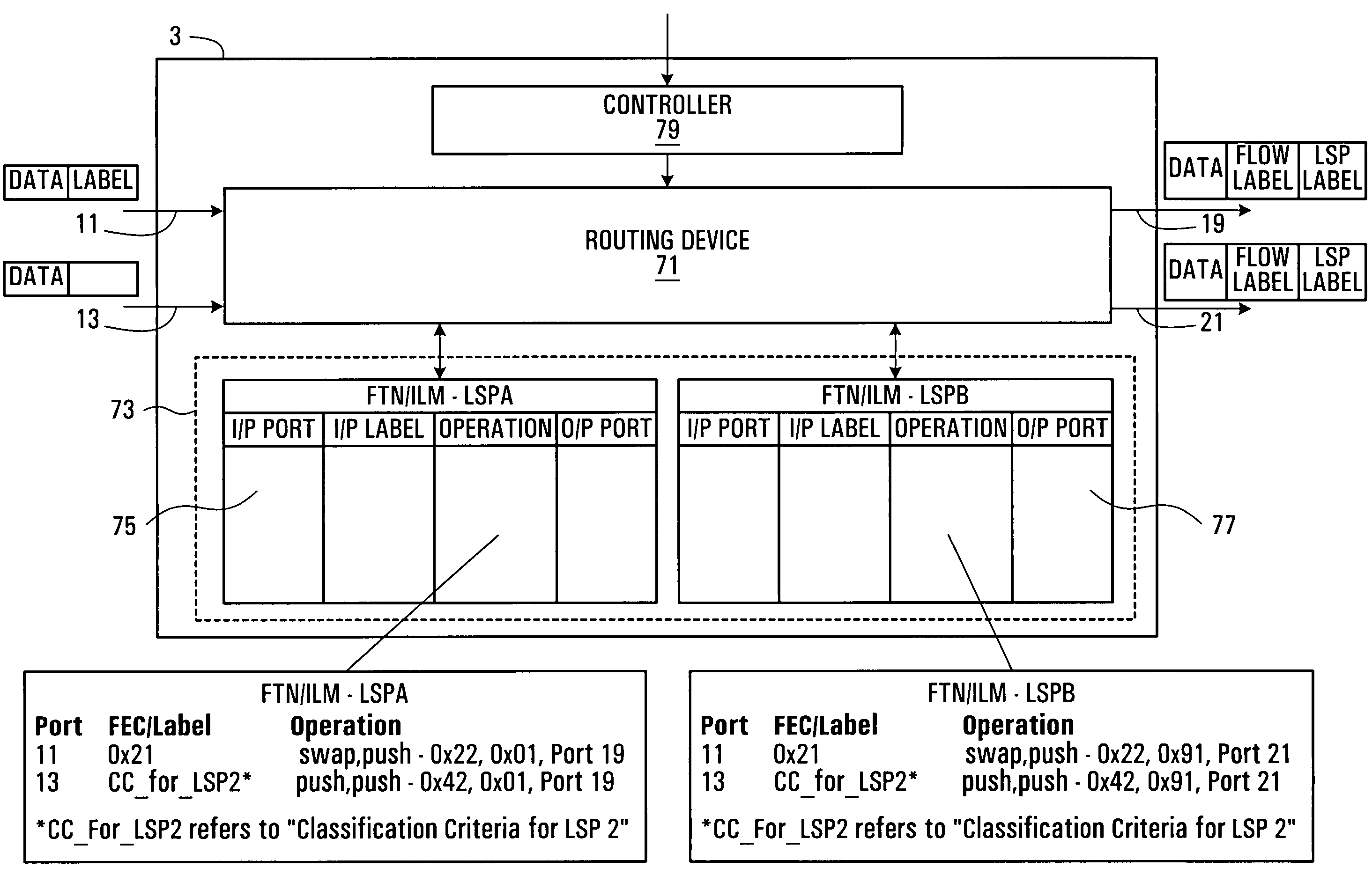
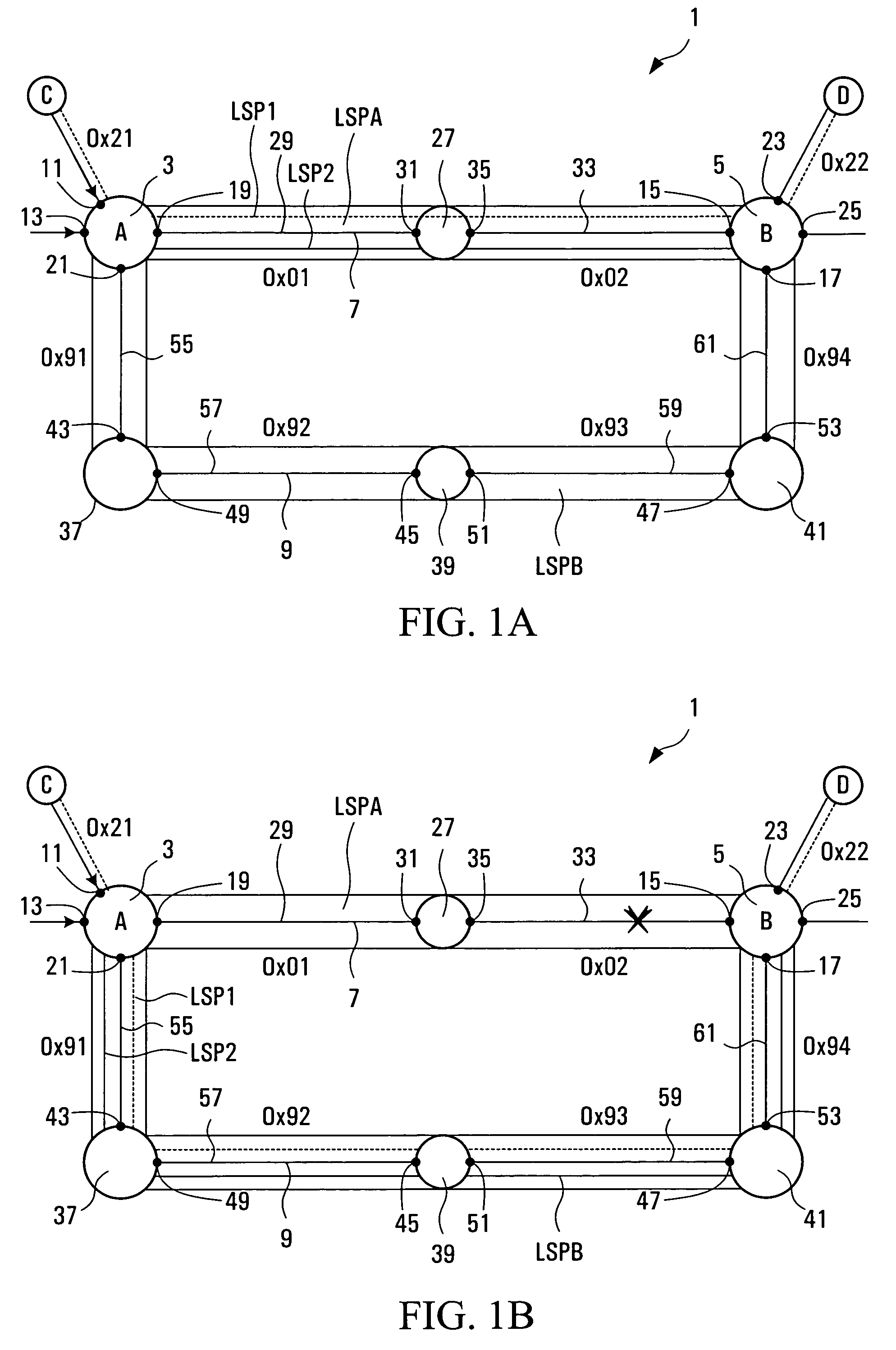
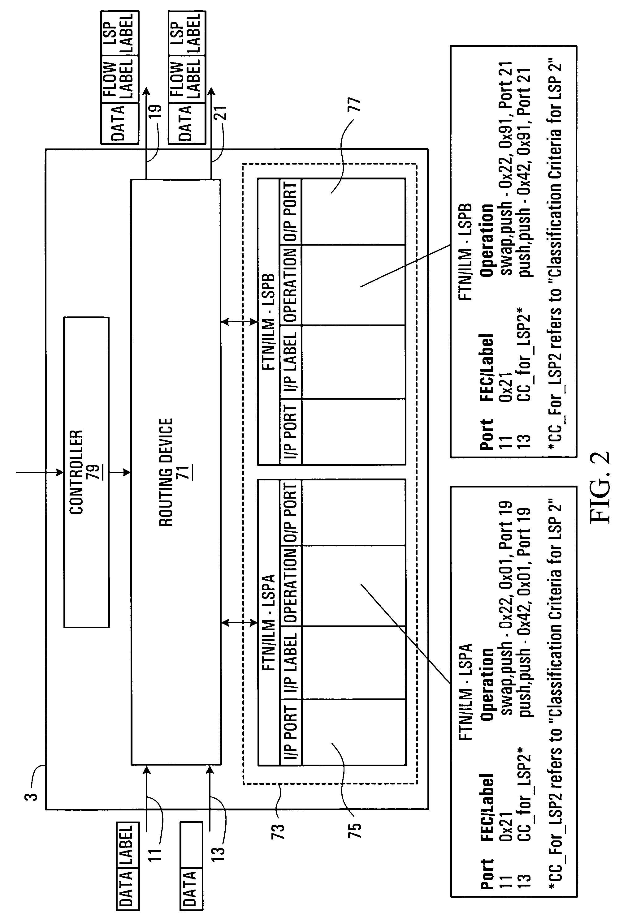
[0025]Referring to FIG. 1, a communication network, in accordance with an embodiment of the present invention, and generally shown at 1, comprises a first switching router 3 at node A, a second switching router 5 at node B and first and second communication paths 7, 9 extending between the first and second switching routers 3, 5. Each of the first and second switching routers 3, 5 has a plurality of input ports 11, 13, 15, 17 and a plurality of output ports 19, 21, 23, 25. The first communication path 7 includes an intermediate switching router 27, a communication link 29 connected from an output port 19 of the first switching router to an input port 31 of the intermediate switching router 27, and a second communication link 33 connected from an output port 35 of the intermediate switching router 27 to an input port 15 of the second switching router 5. The second communication path 9 includes a plurality of intermediate switching routers 37, 39, 41 each having an input port 43, 45, ...


PUM


Abstract

A communication network is provided having source and destination switching routers connected by two different communication paths. A primary label switched path is established on one of the communication paths and a secondary label switched path is established on the other label switched path. The source switching router can be enabled to place one or more data flows within the primary label switched path and can be enabled to place one or more of the same data flows within the secondary label switched path. The destination switching router stores a label identifying each data flow and a forwarding instruction and can be enabled to reference data carried within the primary or secondary LSP with the appropriate data flow label.

Description

FIELD OF THE INVENTION[0001]The present invention relates to a label switched communication network, and in particular to a system and method for controlling the flow of data over a communication network.BACKGROUND OF THE INVENTION[0002]A typical communication network comprises a number of nodes interconnected by communication links, forming communication paths between different nodes on the network. Communication signals are routed over the network from a source node to a predefined destination node over a path which may include a number of nodes and links. Information defining the particular path to be taken and the destination may be carried with the data, for example in a packet header which is read at each node and controls a router at each node to direct the data along the next appropriate communication link of the specified path. This method of data transmission may be referred to as tag or label switching, of which asynchronous transfer mode (ATM) is a well-known example and...

Claims


Application Information

Patent Timeline
IPC IPC(8): H04L1/22H04L12/56
CPCH04L45/00H04L45/22H04L45/28H04L45/50
Inventor CARPINI, WALTER JOSEPHMARK, BARRY DING KENKASVAND HARRIS, ANGELICA GRACE EMELIE
Owner WSOU INVESTMENTS LLC
Features
  • Generate Ideas
  • Intellectual Property
  • Life Sciences
  • Materials
  • Tech Scout
  • Unparalleled Data Quality
  • Higher Quality Content
  • 60% Fewer Hallucinations
Learn More