
Optical fiber composite power cable having loose-tube-type optical fiber impregnated therein

a technology of optical fiber and composite power cables, which is applied in the direction of power cables, cables, instruments, etc., can solve the problems of inability to reduce the optical loss of the cable, and achieve the effect of improving tensile strength, reducing the generation of lateral pressure and thus optical loss

Inactive Publication Date: 2006-10-24
LG CABLE LTD (KR)
View PDF5 Cites 14 Cited by
  • Summary
  • Abstract
  • Description
  • Claims
  • Application Information

AI Technical Summary

Benefits of technology

[0013]Therefore, the present invention has been made in view of the above problems, and it is an object of the present invention to provide an optical fiber composite power cable having a loose-tube-type optical fiber impregnated therein, which has an improved tensile strength and prevents the optical fiber from being compressed by metal conductors, even when excessive tensile force or bending force is applied to the cable, thereby remarkably reducing the generation of lateral pressure and thus optical loss.
[0014]In accordance with the present invention, the above and other objects can be accomplished by the provision of an optical fiber composite power cable having a loose-tube-type optical fiber impregnated therein, comprising metal conductors and the optical fibers surrounded by a single coating layer, wherein the optical fibers are installed in a loose tube made of metal to prevent lateral pressure from being imposed on the optical fibers due to the compressing of the optical fibers by the metal conductors, even when tensile force or bending force is applied to the cable.

Problems solved by technology

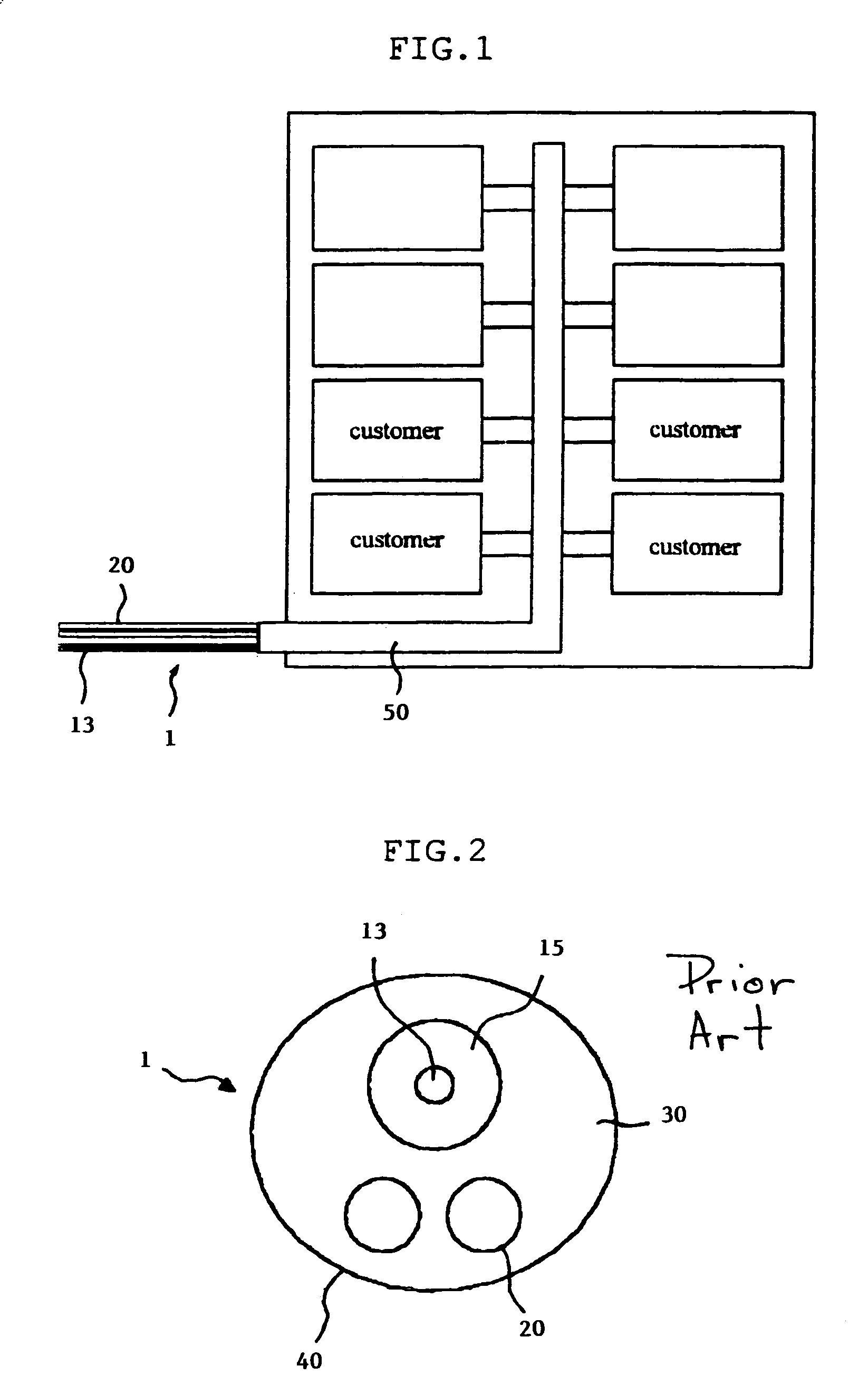
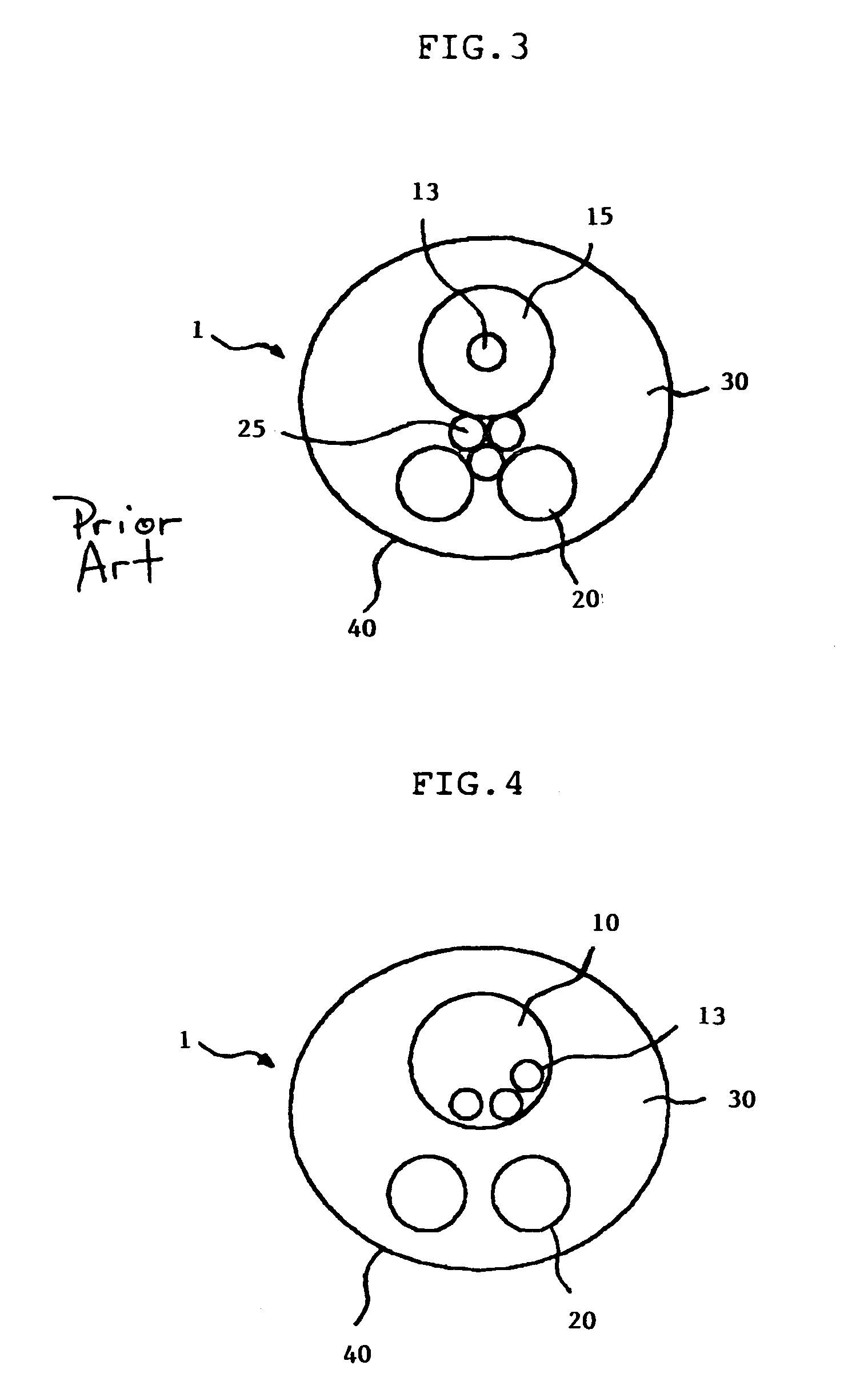
However, since the reinforcement wires 25 compress the optical fiber 13 when tensile force or bending force is applied to the cable 1, they are not strong enough to prevent lateral pressure from being imposed on the optical fiber 13, thus being incapable of reducing optical loss of the cable 1.

Method used


Image

  • Optical fiber composite power cable having loose-tube-type optical fiber impregnated therein
  • Optical fiber composite power cable having loose-tube-type optical fiber impregnated therein
  • Optical fiber composite power cable having loose-tube-type optical fiber impregnated therein

Examples


Embodiment Construction

[0021]Now, a preferred embodiment of the present invention will be described in detail with reference to the annexed drawings.

[0022]The embodiment does not limit the scope and spirit of the invention, but is described exemplarily. Some parts in this embodiment, which are substantially the same as those in the prior art, are denoted by the same reference numerals and terms.

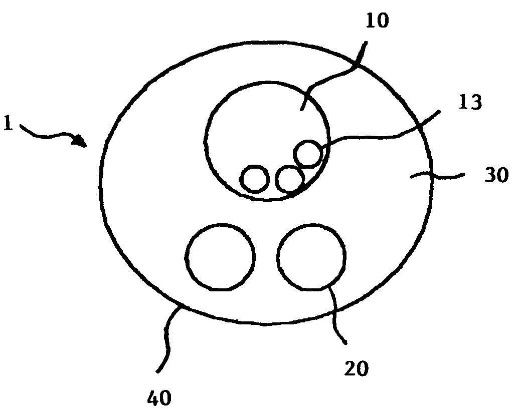
[0023]FIG. 4 is a cross-sectional view of an optical fiber composite power cable in accordance with the present invention.

[0024]As shown in FIG. 4, the optical fiber composite power cable 1 of the present invention comprises metal conductors 20 and optical fibers 13, which are surrounded by the same coating layer 40. The optical fibers 13 are contained in a loose tube 10 made of a metal, thereby preventing lateral pressure from being imposed on the optical fibers 13 due to compression of the optical fibers 13 by the metal conductors 20, even when tensile force or bending force is applied to the cable 1.

[0025]The lo...


PUM

PropertyMeasurementUnit
tensile forceaaaaaaaaaa
bending forceaaaaaaaaaa
tensile strengthaaaaaaaaaa

Abstract

Disclosed is an optical fiber composite power cable having a loose-tube-type optical fiber impregnated therein, wherein the optical fibers are installed in a loose tube made of metal to prevent lateral pressure from being imposed on the optical fibers by the metal conductors, even when tensile force or bending force is applied to the cable.

Description

BACKGROUND OF THE INVENTION[0001]1. Field of the Invention[0002]The present invention relates to an optical fiber composite power cable and more particularly to an optical fiber composite power -able having a loose-tube-type optical fiber impregnated therein which has improved tensile strength and which prevents the optical fiber from being compressed by metal conductors, even when excessive tensile force or bending force is applied to the cable, thereby remarkably reducing the generation of lateral pressure and thus optical loss.[0003]2. Description of the Related Art[0004]Recently, an optical communication method using an optical cable, namely a supreme transmission line for audio and data communication, has been increasingly developed. Thus, optical fiber composite power cables, provided with an optical cable and a power cable, which are impregnated therein, have become popular.[0005]As shown in FIG. 2, an optical power composite interior cable supplied to customers, among the ab...

Claims


Application Information

Patent Timeline
Patent Type & Authority Patents(United States)
IPC IPC(8): G02B6/44H01B9/00H01B11/22
CPCH01B9/005G02B6/4416H01B11/22G02B6/4488
Inventor LEE, SU-KIL
Owner LG CABLE LTD (KR)
Learn More