Supercharge Your Innovation With Domain-Expert AI Agents!

Single-direction cementing plug

a cementing plug and single-direction technology, applied in the direction of sealing/packing, fluid removal, borehole/well accessories, etc., can solve the problems of non-adherence of the casing to the hardened cement, damage to the check valve, and expansion of the casing, so as to prevent the movement of the body

Active Publication Date: 2006-10-31
WEATHERFORD TECH HLDG LLC
View PDF805 Cites 44 Cited by
  • Summary
  • Abstract
  • Description
  • Claims
  • Application Information

AI Technical Summary

Benefits of technology

[0015]Another embodiment comprises a method of installing a cement plug in a well. The method includes running a string of wellbore casing into a wellbore. Then, a quantity of cement is injected into the casing in an amount adequate to fill a predetermined annular volume between the casing and the wellbore therearound. Then, the cement plug is installed at an upper end of the casing. The cement plug includes a body and gripping members for preventing movement of the body towards a surface of the well. The cement plug further includes a sealing member for sealing a fluid path between the body and the casing. Then, the plug is urged downwards to a desired depth in the wellbore with a second fluid. The plug separates the cement therebelow from the second fluid injected above the plug. Then, the gripping members are caused to set, thereby preventing the movement of the plug towards the surface of the well.
[0016]Yet another embodiment comprises a method of installing a cement plug in a well. The method includes drilling a wellbore with a string of casing having a cutting member disposed on a lower portion of the string. Then, a quantity of cement is injected into the casing in an amount adequate to fill a predetermined annular volume between the casing and the wellbore therearound. Then, the cement plug is installed at an upper end of the casing. The cement plug includes a body and gripping members for preventing movement of the body towards a surface of the well. The cement plug further includes a sealing member for sealing a fluid path between the body and the casing. Thereafter, the plug is urged downwards to a desired depth in the wellbore with a second fluid. The plug separates the cement therebelow from the second fluid injected above the plug. Then, the gripping members are caused to set, thereby preventing the movement of the plug towards the surface of the well.

Problems solved by technology

This method, however, expands the casing and creates non-adherence of the casing to the hardened cement after the hydrostatic pressure in the casing is released and the casing string contracts.
One problem with the use of a check valve in preventing the backflow of cement slurry is that flowing a cement slurry or other fluid through the check valve may damage the check valve and may prevent the check valve from functioning properly.
In addition, installing a check valve, even in the open position, on a lower portion of a casing string can cause a pressure surge within the wellbore, thereby damaging surrounding hydrocarbon-bearing formations.
One challenge of drilling with casing is providing a cementing apparatus in the string to facilitate the circulation of cement after the wellbore is formed.
However, because drilling fluid must be circulated through the string as the wellbore is formed, any valve in the string can hamper the circulation of fluid that is necessary for drilling

Method used


Image

  • Single-direction cementing plug
  • Single-direction cementing plug
  • Single-direction cementing plug

Examples


Embodiment Construction

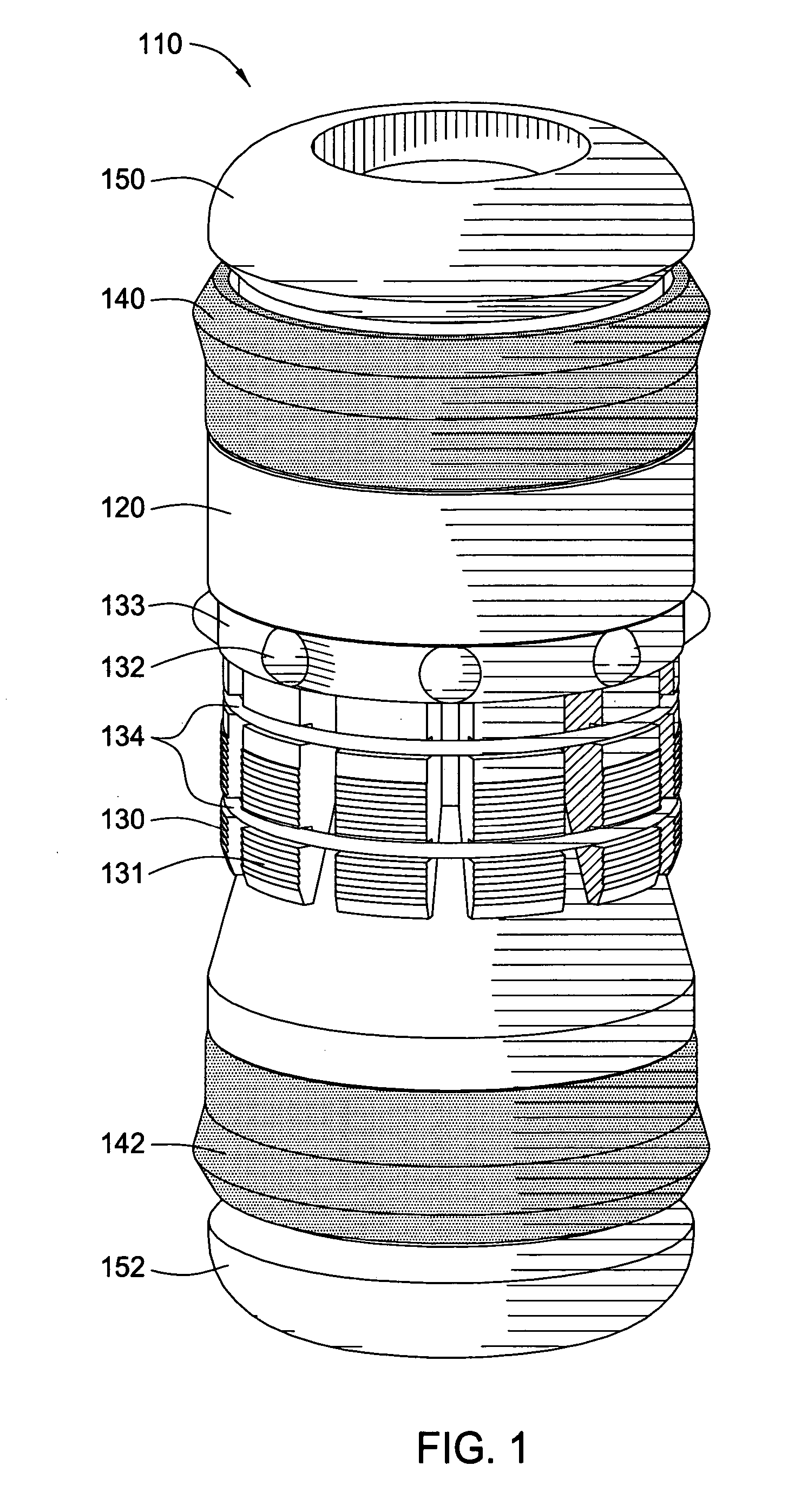
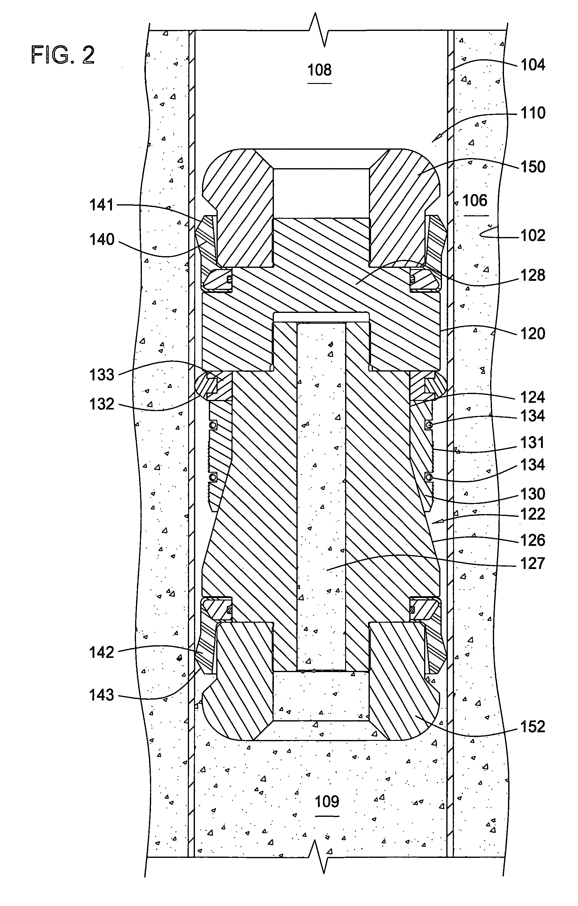
[0033]The present invention generally relates to apparatus and methods for completing a well. Particularly, the present invention relates to a single-direction cementing plug.

[0034]FIG. 1 is a schematic perspective view of one embodiment of a single-direction plug 110. The single-direction plug 110 may include a cylindrical body 120, one or more gripping members 130, a garter spring 134, a drag element 132, sealing members 140, 142, and end caps 150, 152. FIG. 2 is a schematic cross-sectional view of the single-direction plug 110 of FIG. 1 in an unactuated position disposed within a casing 104 lining a portion of a vertical wellbore 102. The annulus 106 between the casing 104 and the wellbore 102 is typically filled with a fluid, such as a cement slurry, to strengthen the walls of the wellbore and facilitate isolation of certain areas of the wellbore. The plug 110 may separate a first fluid 109, such as a cement slurry, from a second fluid 108, such as a displacement fluid, within t...


PUM


Abstract

The present invention generally relates to apparatus and methods for completing a well. Particularly, the present invention relates to a single-direction plug for use with cementing applications and with drilling with casing applications. One embodiment comprises a cement plug for installation in a wellbore casing. The plug includes a body and gripping members for preventing movement of the body in a first axial direction relative to the casing. The plug further comprises a sealing member for sealing a fluid path between the body and the casing. The plug is movable in a second axial direction with fluid pressure but is not movable in the first direction due to fluid pressure.

Description

CROSS-REFERENCE TO RELATED APPLICATIONS[0001]This application claims benefit of U.S. Provisional Patent Application Ser. No. 60 / 443,768, filed Jan. 30, 2003, which application is herein incorporated by reference in its entirety.BACKGROUND OF THE INVENTION[0002]1. Field of the Invention[0003]The present invention generally relates to apparatus and methods for completing a well. Particularly, the present invention relates to positioning a plug in a wellbore. More particularly, the present invention relates to a single-direction plug for use in well completions and drilling with casing applications.[0004]2. Description of the Related Art[0005]In the oil and gas producing industry, the process of cementing casing into the wellbore of an oil or gas well generally comprises several steps. For example, a string of casing is run in a wellbore to the required depth. Then, cement slurry is pumped into the casing to fill an annulus between the casing and the wellbore wall to a desired height. ...

Claims


Application Information

Patent Timeline
Patent Type & Authority Patents(United States)
IPC IPC(8): E21B33/13E21B33/134E21B33/16
CPCE21B33/134E21B33/16E21B33/129
Inventor GIROUX, RICHARD L.BRUNNERT, DAVID J.GALLOWAY, GREGORY GUYJORDAN, JOHN C.
Owner WEATHERFORD TECH HLDG LLC
Features
  • R&D
  • Intellectual Property
  • Life Sciences
  • Materials
  • Tech Scout
  • Unparalleled Data Quality
  • Higher Quality Content
  • 60% Fewer Hallucinations
Learn More