Inertia valve shock absorber

a technology of inertia valve and shock absorber, which is applied in the direction of shock absorbers, cycle equipment, transportation and packaging, etc., can solve the problems of preventing the operation of the inertia valve, inhibiting or even reducing the delay, and commercial inertia valve shock absorbers have only enjoyed limited success

Inactive Publication Date: 2006-10-31
FOX FACTORY
View PDF169 Cites 185 Cited by
  • Summary
  • Abstract
  • Description
  • Claims
  • Application Information

AI Technical Summary

Benefits of technology

[0015]A preferred embodiment is a shock absorber including a first fluid chamber, a second fluid chamber, and a fluid circuit connecting the first fluid chamber and the second fluid chamber. An inertia valve includes an inertia mass and a stop. The inertia mass is movable between a first position and a second position. The inertia valve permits a first rate of fluid flow through the fluid circuit in the first position of the inertia mass and a second rate of fluid flow through the fluid circuit in the second position of the inertia mass. The second rate of fluid flow is non-equal to the first rate. One of the inertia mass and the stop defines a pocket for receiving the other of the inertia mass and the stop in the second position of the inertia mass. A first refill passage connects the second fluid chamber and the pocket and restricts fluid flow therethrough from the second fluid chamber to the pocket to provide a delay in movement of the inertia mass toward the first position. A second refill passage connects the second fluid chamber and the pocket and a pressure actuated valve substantially prevents fluid flow between the second fluid chamber and the pocket through the second refill passage below a predetermined threshold pressure differential between the second fluid chamber and the first fluid chamber. The pressure actuated valve permits fluid flow between the second fluid chamber and the pocket through the second refill passage at, or above, a predetermined threshold pressure differential between the second fluid chamber and the first fluid chamber, thereby reducing or eliminating the delay.

Problems solved by technology

Despite the apparent potential, and a long history of numerous attempts to utilize inertia valves in vehicle suspension, commercial inertia valve shock absorbers have enjoyed only limited success.
Most attempted inertia valve shock absorbers have suffered from unresponsive or inconsistent operation due to undesired extraneous forces acting on the inertia valve.
These extraneous forces may result from manufacturing limitations and / or external sources and often inhibit, or even prevent, operation of the inertia valve.
Further, there are currently no commercially available inertia valve shock absorbers for off-road bicycle, or mountain bike, applications.
The problems associated with the use of inertia valves, mentioned above in relation to other vehicles, are magnified in the environment of lightweight vehicles and the relatively small size of mountain bike shock absorbers.

Method used


Image

  • Inertia valve shock absorber
  • Inertia valve shock absorber
  • Inertia valve shock absorber

Examples


Embodiment Construction

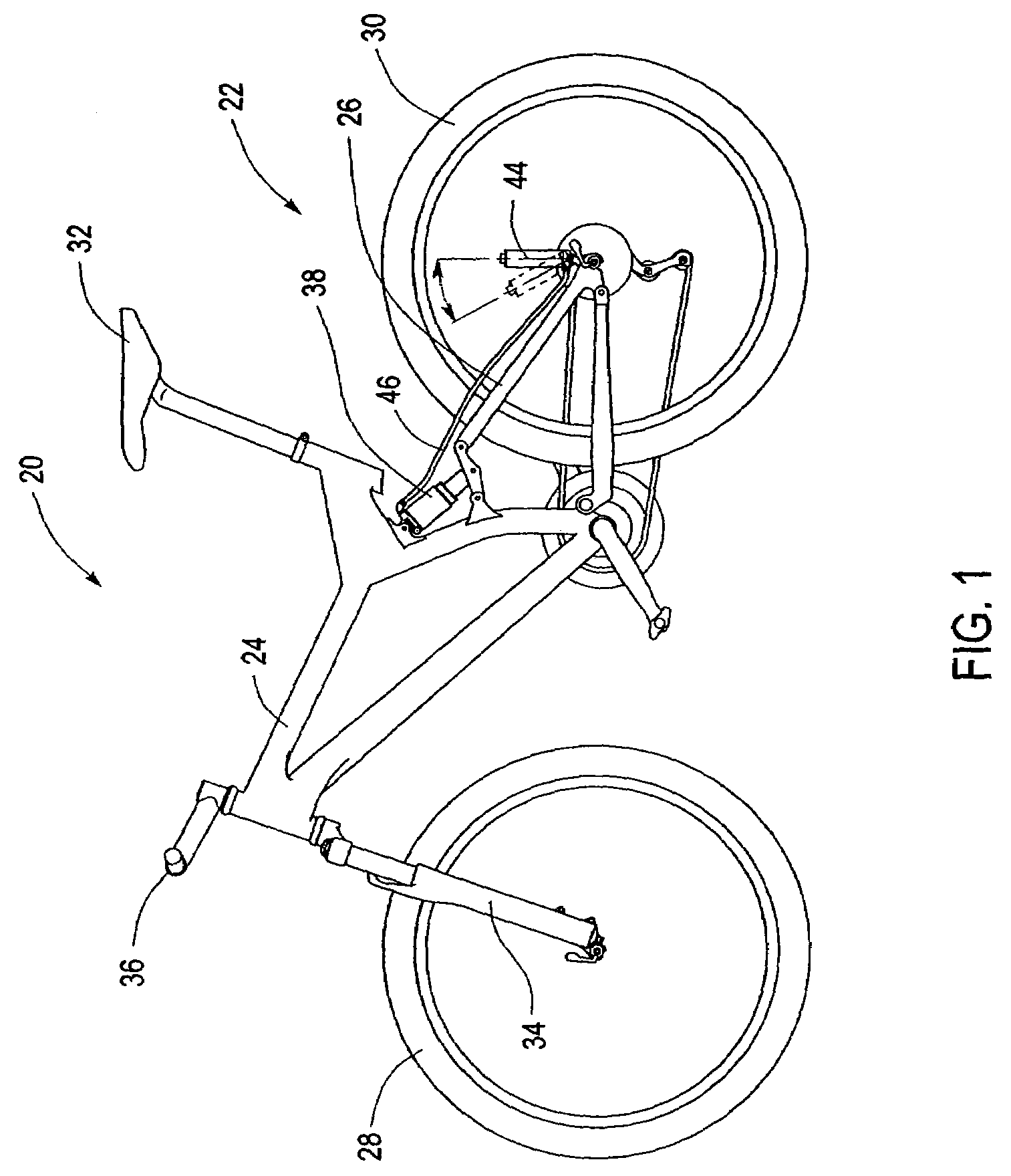
[0058]FIG. 1 illustrates an off-road bicycle, or mountain bike, 20 including a frame 22 which is comprised of a main frame portion 24 and a swing arm portion 26. The swing arm portion 26 is pivotally attached to the main frame portion 24. The bicycle 20 includes front and rear wheels 28, 30 connected to the main frame 24. A seat 32 is connected to the main frame 24 and provides support for a rider of the bicycle 20.

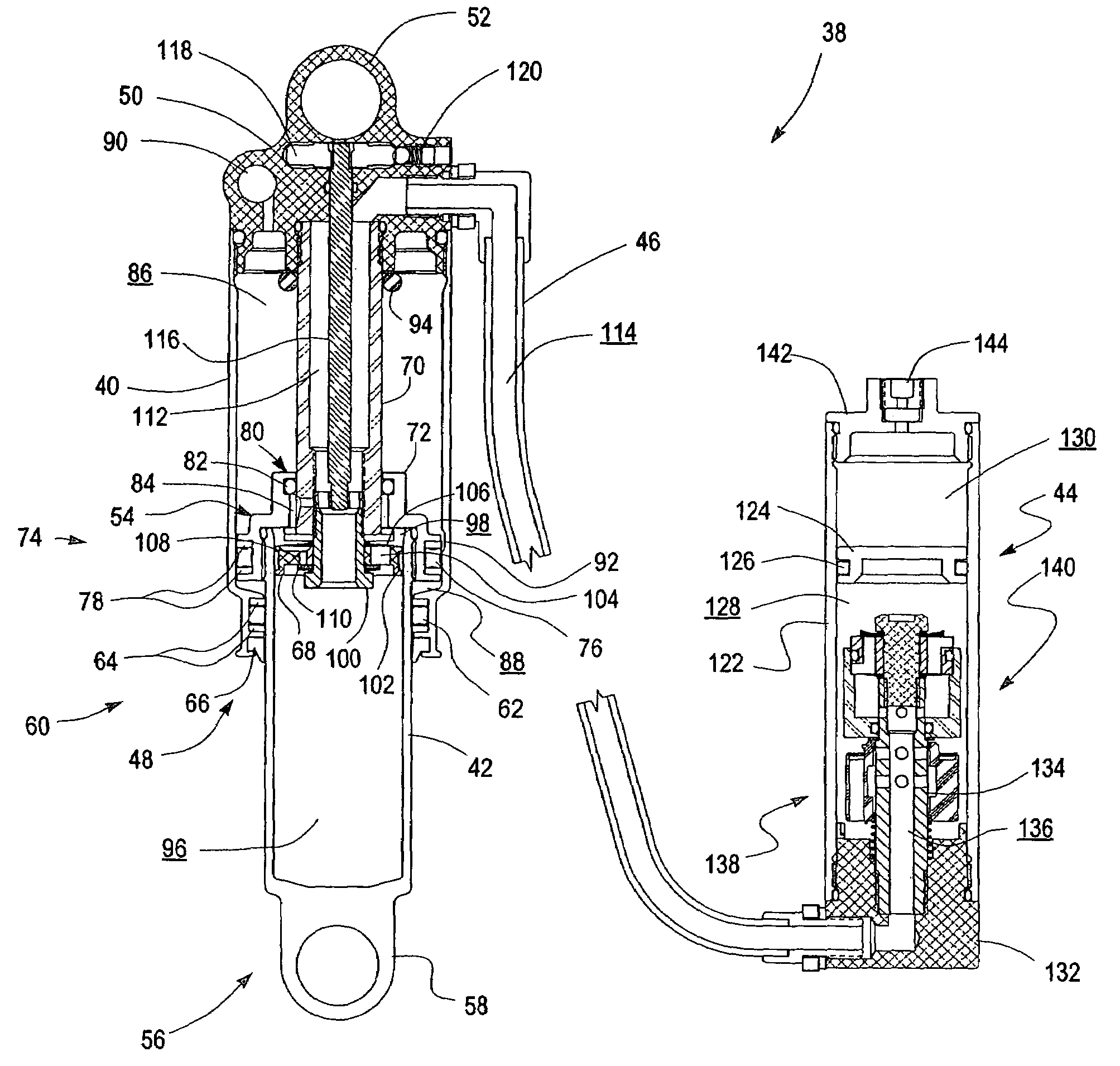
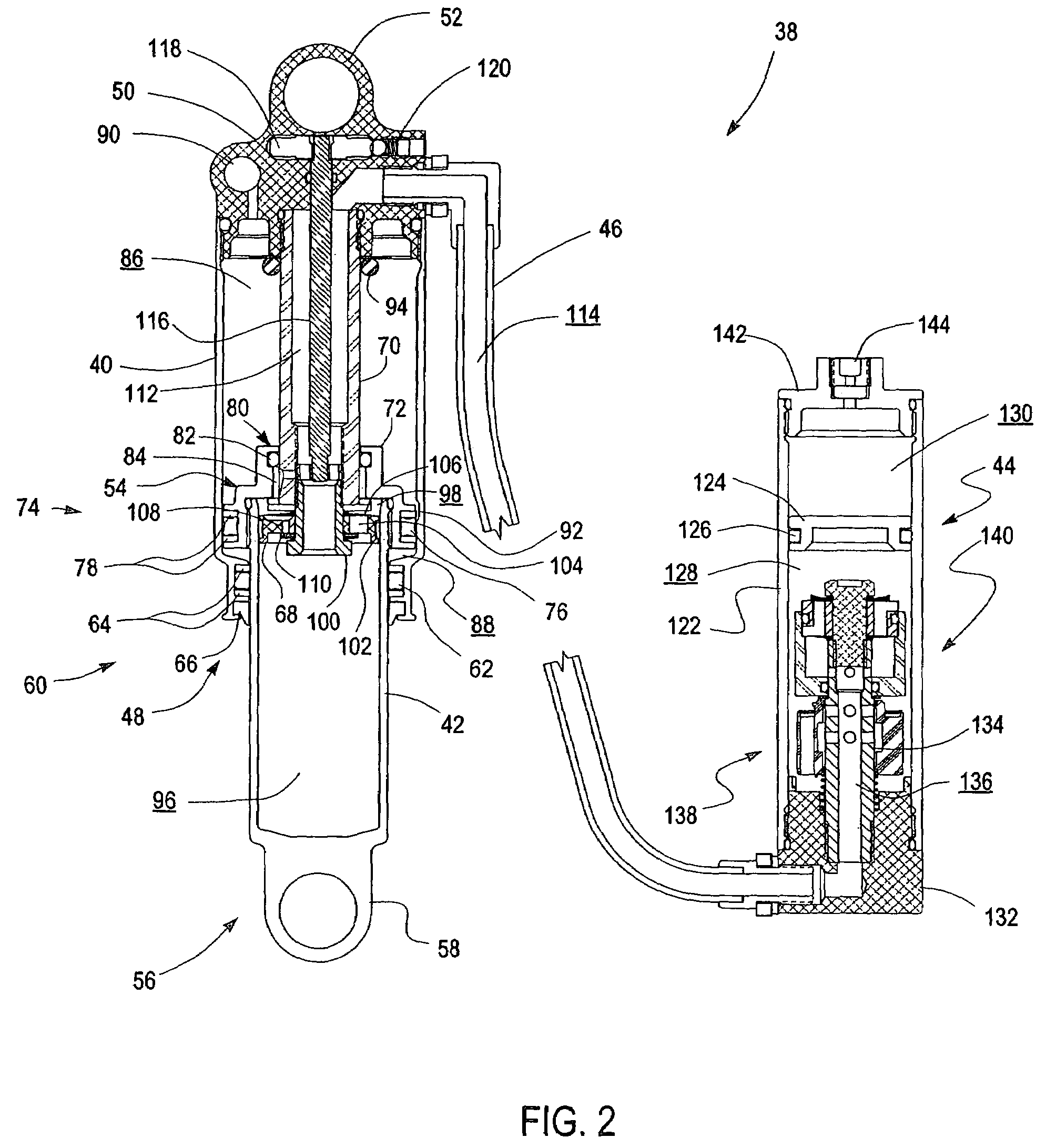
[0059]The front wheel 28 is supported by a preferred embodiment of a suspension fork 34 which, in turn, is secured to the main frame 24 by a handlebar assembly 36. The rear wheel 30 is connected to the swing arm portion 26 of the frame 22. A preferred embodiment of a rear shock 38 is operably positioned between the swing arm 26 and the main frame 24 to provide resistance to the pivoting motion of the swing arm 26. Thus, the illustrated bicycle 20 includes suspension members 34, 38 between the front and rear wheels 28, 30 and the frame 22, which operate to substantially re...


PUM

PropertyMeasurementUnit
internal diameteraaaaaaaaaa
pressuresaaaaaaaaaa

Abstract

A damper including a valve movable between an open position and a closed position to selectively alter the compression damping rate of the shock absorber. The valve may include a self-centering feature that operates to keep the valve body centered about the valve shaft. The damper may also include a timer feature, which retains the valve in an open position for a predetermined period of time after it is initially opened.

Description

RELATED APPLICATIONS[0001]This application is a continuation-in-part of U.S. patent application Ser. No. 10 / 378,091, filed Feb. 28, 2003, now abandoned, which is a continuation-in-part of U.S. patent application Ser. No. 10 / 043,079, filed Jan. 9, 2002, issued as U.S. Pat. No. 6,581,948, and U.S. patent application Ser. No. 10 / 042,767, filed Jan. 9, 2002, issued as U.S. Pat. No. 6,604,751, which claim priority from U.S. Provisional Patent Application No. 60 / 329,042, filed Oct. 12, 2001 and U.S. Provisional Patent Application No. 60 / 316,442, filed Aug. 30, 2001, and this application also claims priority from U.S. Provisional Patent Application No. 60 / 451,303, filed Feb. 28, 2003 and U.S. Provisional Patent Application No. 60 / 451,318, filed Feb. 28, 2003, the entireties of which are hereby expressly incorporated by reference herein and made a part of this specification.BACKGROUND OF THE INVENTION[0002]1. Field of the Invention[0003]The present invention relates to vehicle suspensions s...

Claims


Application Information

Patent Timeline
Patent Type & Authority Patents(United States)
IPC IPC(8): F16F9/42B62K25/04B62K25/08B62K25/28F16F9/096F16F9/504
CPCB62K25/04B62K25/08B62K25/286F16F9/096F16F9/466F16F9/504B62K2025/048F16F9/064F16F9/34Y10T29/494
Inventor FOX, ROBERT C.
Owner FOX FACTORY
Why Eureka
Try Eureka