Horizontally draining artificial turf system

a technology of artificial turf and horizontal draining, which is applied in the direction of sewage draining, sewer systems, ways, etc., can solve the problems of less stable base, and achieve the effect of increasing the stability of the bas

Active Publication Date: 2006-10-31
DAWSON HLDG L L C
View PDF14 Cites 23 Cited by
  • Summary
  • Abstract
  • Description
  • Claims
  • Application Information

AI Technical Summary

Benefits of technology

[0006]It is an aspect of the present general inventive concept is to provide an artificial turf, which allows rainwater to evacuate efficiently without infiltrating its stone base, thereby increasing the stability of the base.
[0007]Another aspect of the present general inventive concept is to provide an artificial turf that is easy to maintain, thereby reducing the maintenance costs. Yet another aspect of the present general inventive concept is to provide a method for constructing artificial turf that has a horizontally draining system.
[0011]The drainage blanket is a piece of solid slab containing sufficiently large and properly distributed continuous void, allowing water to flow in at least one direction. Alternatively, it may consist of a rigid solid cupsated core, covered by one or more water impermeable sheets. To build a large artificial playing field, two or more pieces of drainage blankets may be jointed by a watertight seam so that water cannot pass through the joint to reach the base. In this way, a monolithic full area impermeable drainage blanket is created.
[0012]The present general inventive concept provides a method for quickly and economically constructing an artificial turf playing field, which has reduced engineering risks and increased water evacuation capacities. The method is especially useful when poor soils or unfavorable site drainage conditions are encountered. In addition, a method is provided for determining the necessary water-evacuating capacity for a given artificial turf system, therefore reducing engineering risks.
[0013]The artificial turf system of the present general inventive concept has one or more of the advantages. In one aspect, rainwater does not get into the base of the invented artificial turf system, and therefore, the infiltration property of the base is no longer necessary provided that the entire drainage blanket has been designed with a sufficient flow capacity to provide the required evacuation rate. In another aspect, when an impermeable drainage blanket is used, the base is better protected and its installation life is extended.
[0014]In yet another aspect, the drainage blanket under the artificial turf system may act as an excellent shock attenuation pad. By designing the structure of the drainage blanket, different degrees of the shock attenuation may be achieved. Finally, when the base is constructed by missing onsite soils with a soil stabilizer to form a strong, durable and water-impervious base, it is unnecessary to excavate, export or import soils to or from the site, thereby reducing construction costs and time. Incorporation of the soil stabilizer in the base also increases the stability of the base and the playing field.

Problems solved by technology

However, such base was less stable, especially with regard to maintaining the high tolerance finish grade, throughout the life out of the turf.

Method used


Image

  • Horizontally draining artificial turf system
  • Horizontally draining artificial turf system
  • Horizontally draining artificial turf system

Examples


Embodiment Construction

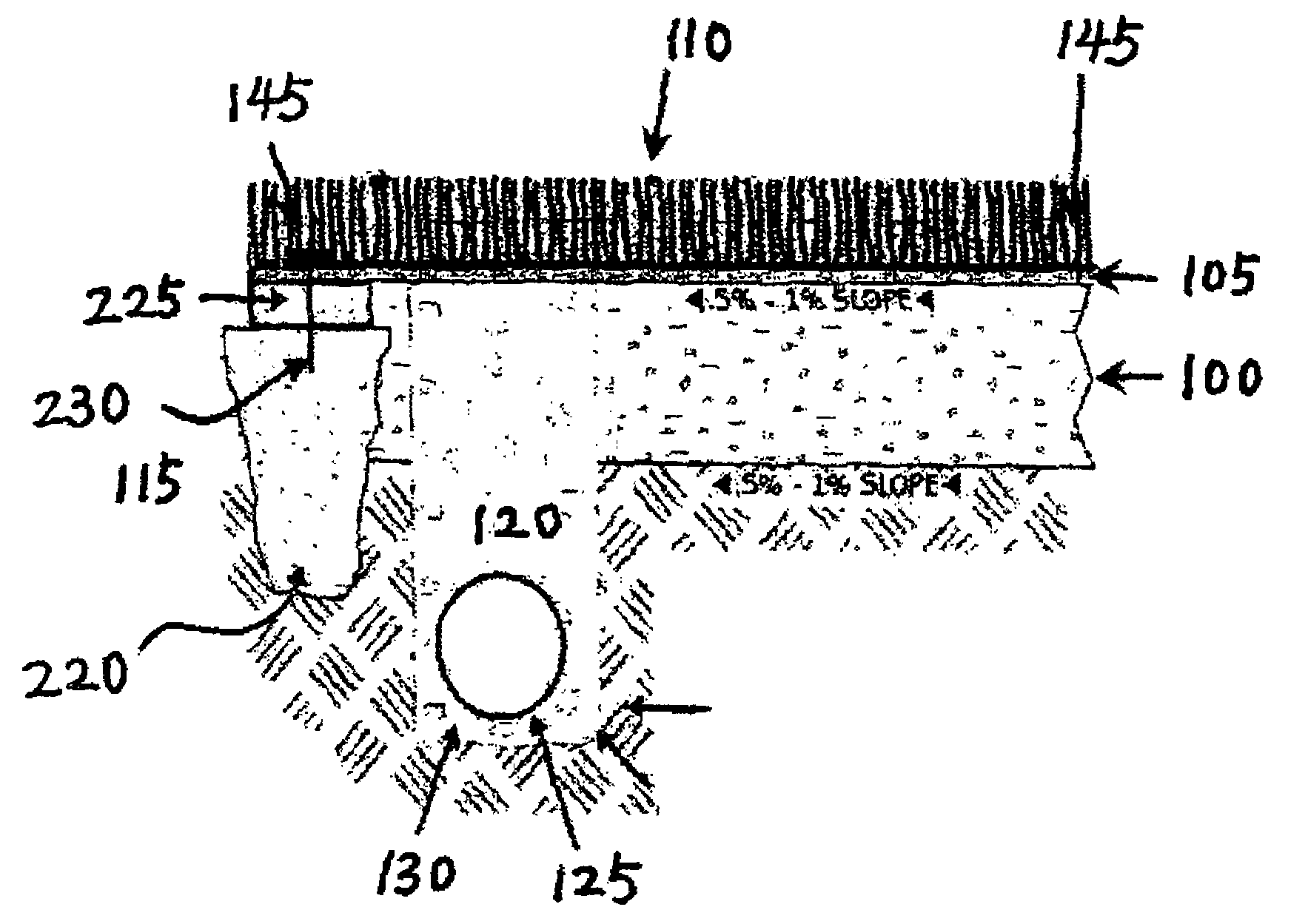
[0024]FIG. 1 is a cross-sectional view of the structure of the vertically draining artificial turf system, according to an embodiment.

[0025]In an embodiment of the present general inventive concept, the horizontally draining artificial turf system can include a base 100 built with a sufficient degree of slope, a drainage blanket 105 above the base 100, an artificial turf 110 over the drainage blanket 105, fastening mechanism 115 to attach the artificial turf 110 onto the base 100, and a draining apparatus 120, which is situated near and below the lower edge of the base 100. the artificial turf is 110 is water permeable or perforated, allowing water to drain vertically to reach the drainage blanket 105. The draining apparatus 120, consisting of a perforated pipe 125 and surrounding washing sands or stones 130, is directly under the opening or perforated edge of the drainage blanket 105 near the lower edge of the base 100 so that the water from the drainage blanket 105 is able to flow...


PUM


Abstract

A horizontally draining artificial turf system comprises an impervious base at proper slope, an impermeable layer or drainage blanket over the base at a corresponding slope for guiding water horizontally, an artificial turf at top of the impermeable layer, and a perforated pipe near the lower edge of the base for receiving water for evacuation. Rainwater over the artificial turf first drains vertically onto the impermeable layer and then flows along the impermeable layer to reach the perforated pipe, without infiltrating into the base. Alternatively, a partially pervious drainage blanket is provided in lieu of the impermeable layer where the base is partially pervious. Backup rainwater runs off the drainage blanket horizontally after it saturates the soils of the base.

Description

CROSS REFERENCE TO RELATED APPLICATIONS[0001]This application claims benefit and priority from provisional application No. 60 / 526,371, filed on Dec. 2, 2003, entitled, “Horizontally Draining Artificial Turf System,” which is incorporated by reference herein in its entirety. This application also claims benefit and priority from provisional application No. 60 / 567,085, filed on Apr. 30, 2004, entitled, “Method for Turf Installation Utilizing Micromechanical Bonding,” which is incorporated by reference herein in its entirety. This application is also a continuation in part (CIP) of application Ser. No. 10 / 869,063, Jun. 17, 2004, entitled, “Method of Manufacturing Synthetic Turf,” which is incorporated by reference herein in its entirety and which claims priority to provisional application No. 60 / 520,185 Nov. 15, 2003 which is also incorporated by reference herein in its entirety.FIELD OF THE INVENTION[0002]The present general inventive concept relates to artificial playing surfaces for...

Claims


Application Information

Patent Timeline
Patent Type & Authority Patents(United States)
IPC IPC(8): E02B11/00E01C13/08E03F1/00
CPCE01C13/08
Inventor DALUISE, DANIEL A.
Owner DAWSON HLDG L L C
Why Eureka
Try Eureka