Tooth elevator

Inactive Publication Date: 2006-10-31
SOHN JUNG W
View PDF19 Cites 24 Cited by
  • Summary
  • Abstract
  • Description
  • Claims
  • Application Information

AI Technical Summary

Benefits of technology

[0012]In one variant of the invention, the mating jaw portions include a downward angled offset. The offset allows a practitioner to mor

Problems solved by technology

The straight elevator can be problematic as it is difficult to control the force applied to such a tool.
This practice can result in broken teeth and related complications.
Further, the Rodriguez del Val forceps uses an a

Method used


Image

  • Tooth elevator
  • Tooth elevator
  • Tooth elevator

Examples


Embodiment Construction

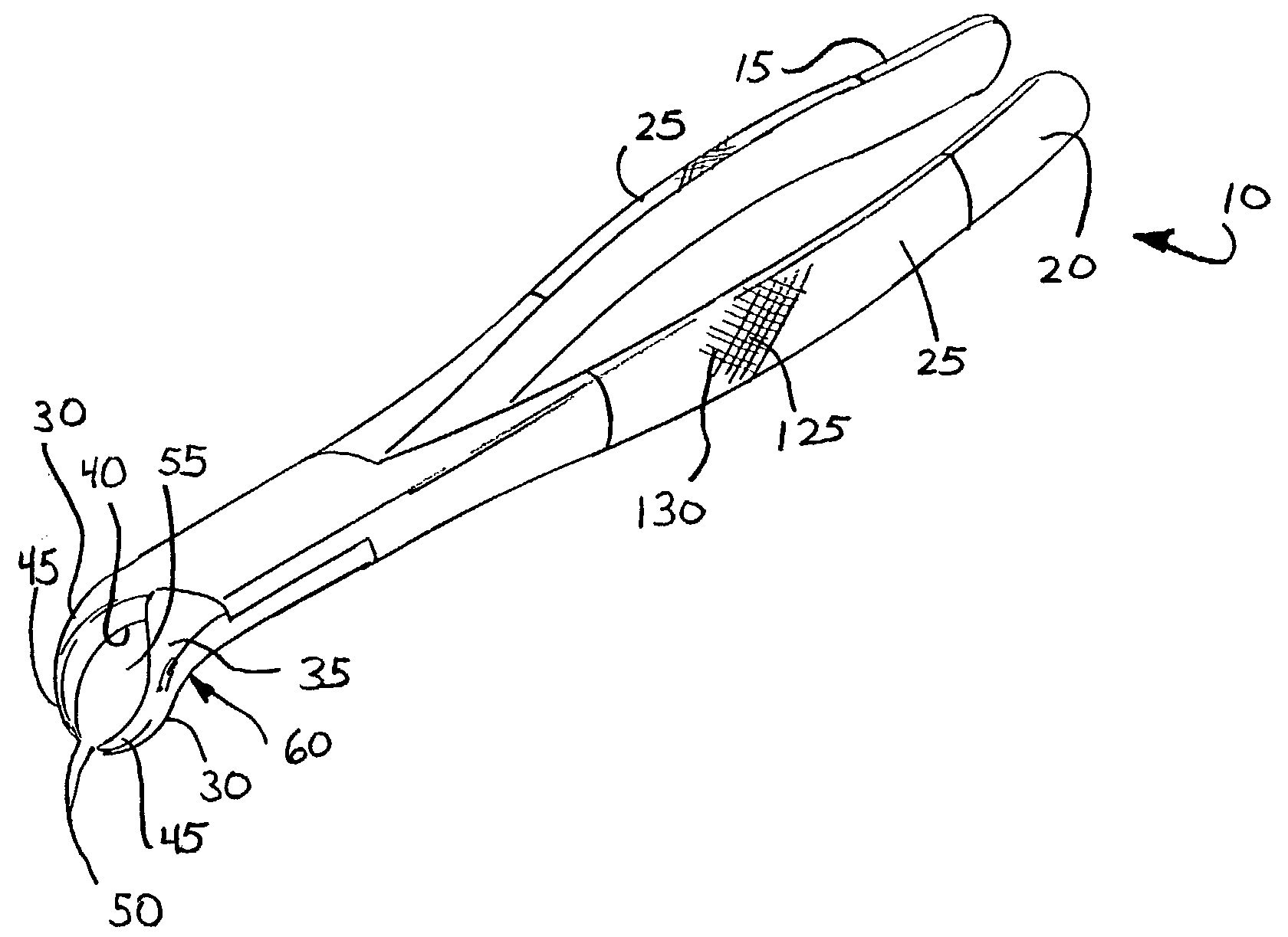
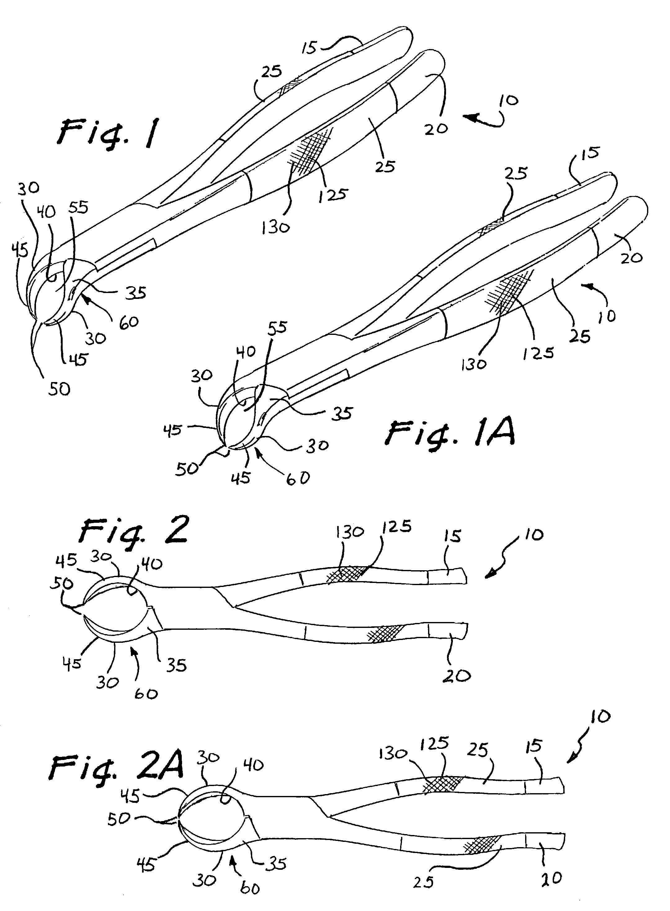
[0026]FIGS. 1–6 illustrate a tooth elevator 10 which may be constructed from the following components. First 15 and second 20 mating side members are provided. Each of the side members 15, 20 has a handle portion 25 and a mating jaw portion 30. The jaw portion 30 extends forwardly from the handle portion 25. The first side member 15 is hingedly attached to the second side member 20 between the jaw portion 30 and the handle portion 25.

[0027]Each of the mating jaw portions 30 are wedge shaped in cross-section and have an angled front face 35, a rear face 40, and inward curving side members 45 tapering to a point 50. The mating jaw portions 30 form an elongated ovoid shape 55 when in a closed position 60.

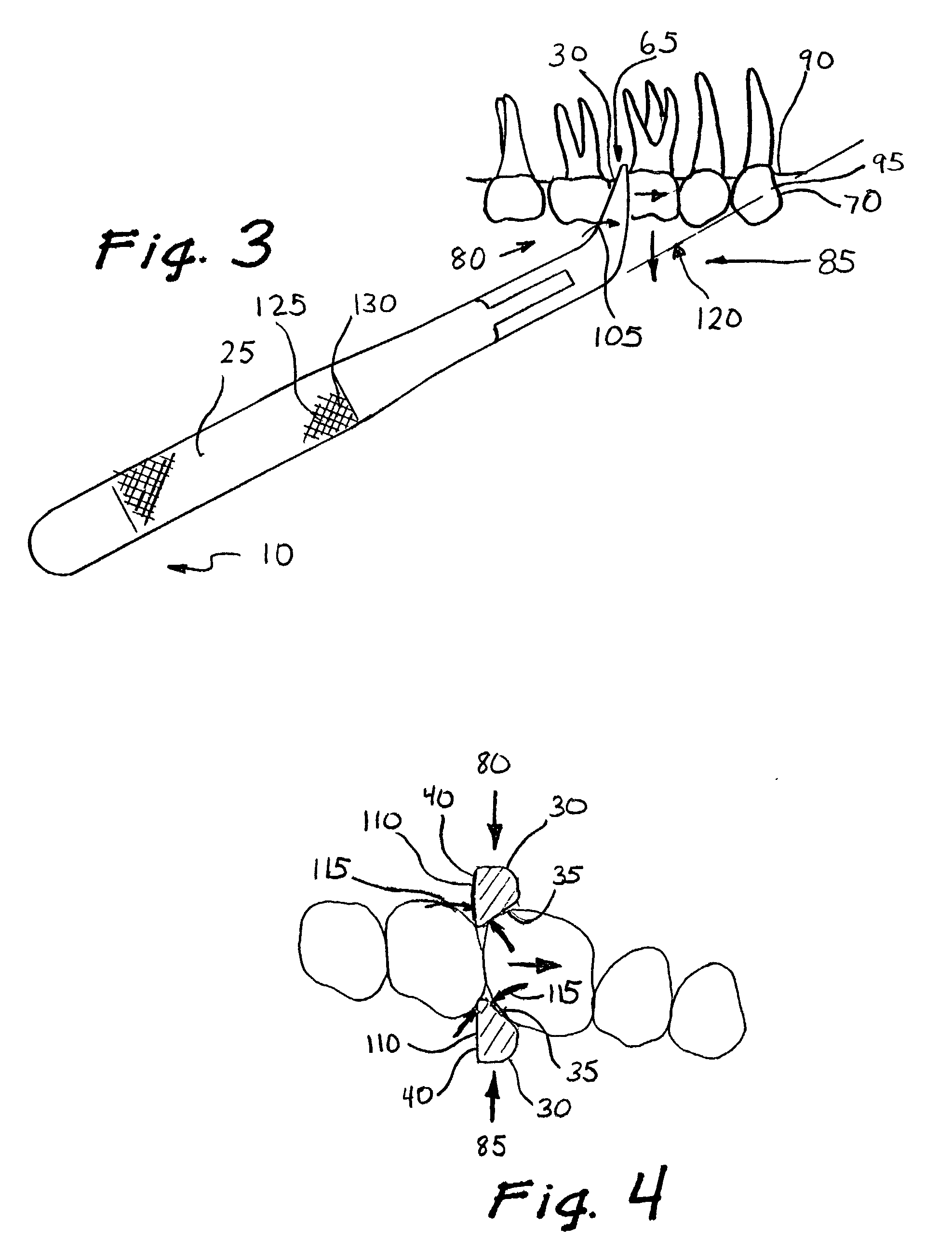
[0028]The mating jaw portions 30 are inserted into a sulcus 65 of either of an upper 70 or lower 75 molar from buccal 80 and opposite 85 sides, as illustrated in FIGS. 3, 4, 5 and 6.

[0029]As force is applied to the handle portions 25, the mating jaw portions 30 are urged together betwe...


PUM


Abstract

A tooth elevator designed to minimize risk of injury to a patient's mouth or adjacent teeth during tooth extraction is described. The elevator has mating side members, a handle portion and a mating jaw portion. As force is applied to the handle portions, the jaw portions are urged together on either side of a molar to be extracted. Inward curving side members disjoint the tooth upwardly while an angled front face simultaneously moves the tooth back, loosening it for extraction. A variation of the tooth elevator has a downward angled offset that allows a practitioner to easily position the elevator in a patient's mouth without the discomfort of raising the elbow of the grasping hand. The handle portions may also have non-slip features.

Description

FIELD OF INVENTION[0001]The invention pertains to dental tools. More particularly, the invention relates to the tooth elevators designed to minimize the risk of injury to a patient or damage to adjacent teeth when removing a tooth.BACKGROUND OF THE INVENTION[0002]Various tools and devices have been developed for elevating teeth during the extraction process. The most common device used for this purpose is the straight elevator. This tool consists of a handle, a straight shaft and a rounded, scoop shaped tip. The elevator is placed perpendicular to the long axis of the alveolar ridge on the mesial aspect of the tooth, with the rounded side of its tip resting on the bone. The elevator is rotated away from the tooth, creating a “scooping” action to elevate the tooth. The elevator may also be rotated toward the tooth to luxate and move it posteriorly. The straight elevator can be problematic as it is difficult to control the force applied to such a tool. If the practitioner slips while ...

Claims


Application Information

Patent Timeline
IPC IPC(8): A61C3/14B25B7/02
CPCA61C3/14
Inventor SOHN, JUNG W.
Owner SOHN JUNG W
Why Eureka
Try Eureka