Controlled load limited switch dynamic logic circuitry

a dynamic logic circuit and load limitation technology, applied in logic circuits, pulse techniques, electrical apparatuses, etc., can solve the problems of clock loads dominating circuit power dissipation, cycle may consume power, and it is difficult to implement selection circuits for single and multi-level selection from many inputs

Inactive Publication Date: 2006-10-31
INT BUSINESS MASCH CORP
View PDF4 Cites 12 Cited by
  • Summary
  • Abstract
  • Description
  • Claims
  • Application Information

AI Technical Summary

Problems solved by technology

However, the switching of the output node with the toggling of the phase of the clock each cycle may consume power even when the logical value of the output is otherwise unchanged.
Computer systems employing dynamic logic may find that it is difficult to implement selection circuits for single and multilevel selection from many inputs because of the limitations of required precharge and evaluation times as well as the fact that outputs are not held during the precharge cycle.
However, LSDL circuitry pre-charges the dynamic node with the clock and thus the pre-charge device represents a load to the clock tree.
When the clock frequency is very high, clock loads begin to dominate circuit power dissipation.

Method used


Image

  • Controlled load limited switch dynamic logic circuitry
  • Controlled load limited switch dynamic logic circuitry
  • Controlled load limited switch dynamic logic circuitry

Examples


Embodiment Construction

[0030]In the following description, numerous specific details are set forth to provide a thorough understanding of the present invention. For example, specific logic functions and the circuitry for generating them may be described; however, it would be recognized by those of ordinary skill in the art that the present invention may be practiced without such specific details. In other instances, well-known circuits have been shown in block diagram form in order not to obscure the present invention in unnecessary detail. Refer now to the drawings wherein depicted elements are not necessarily shown to scale and wherein like or similar elements are designated by the same reference numeral by the several views.

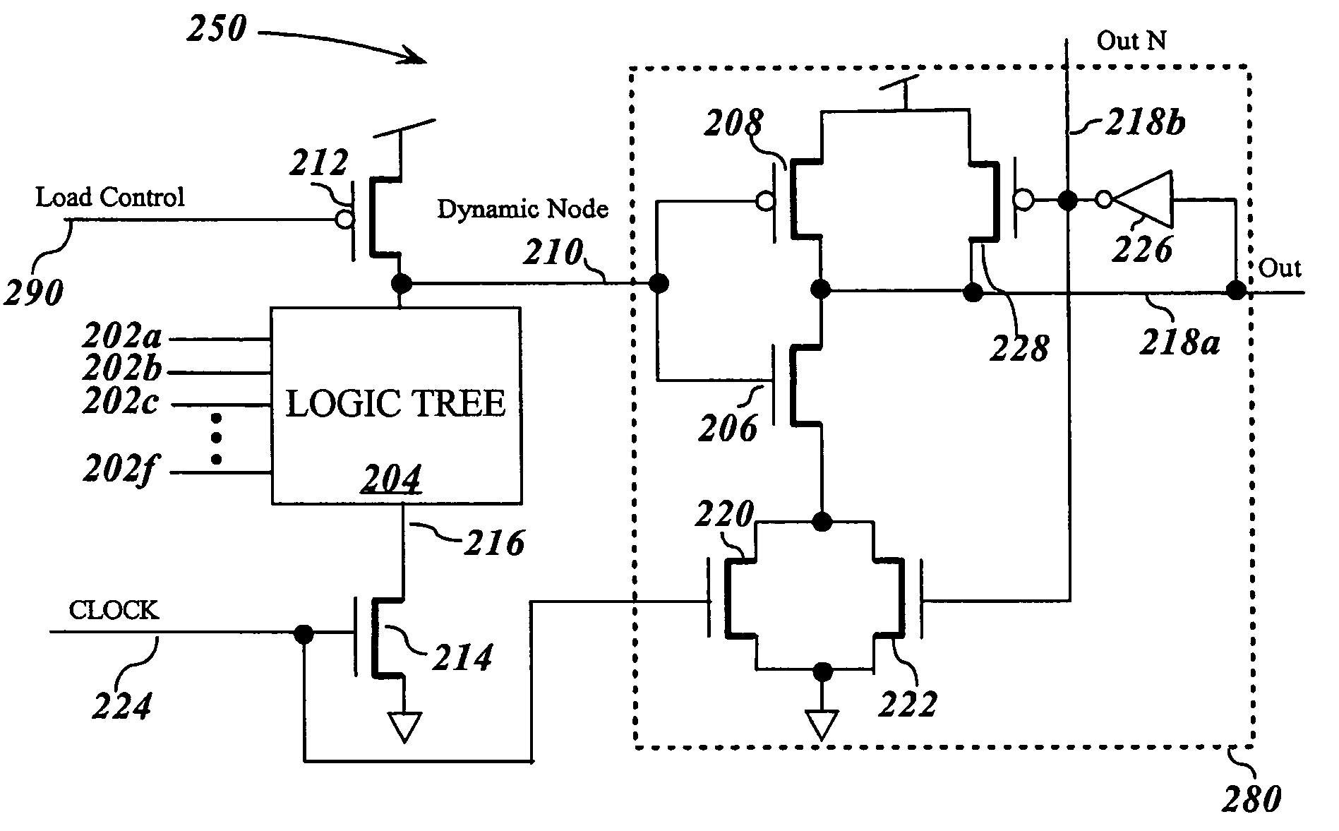
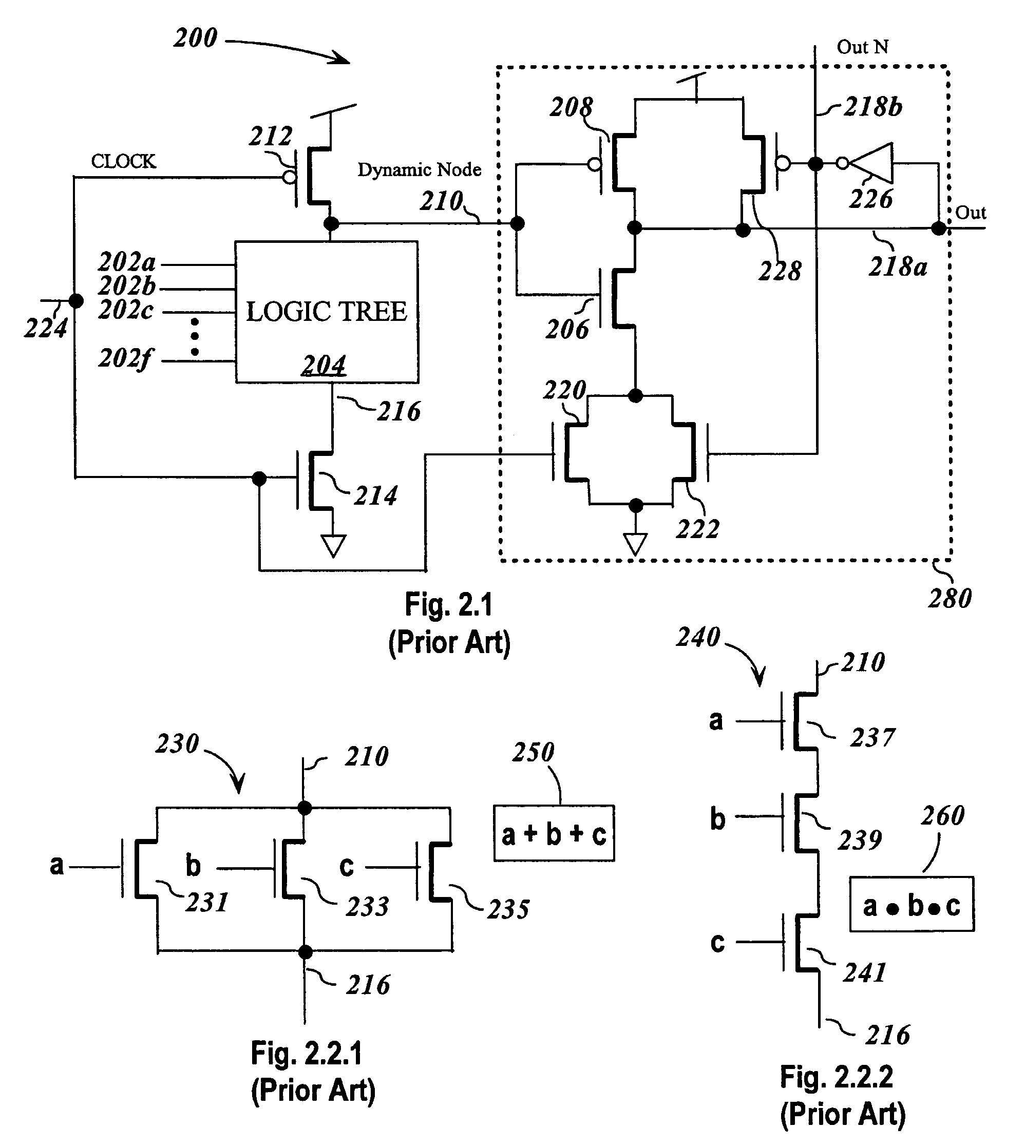
[0031]FIG. 2.1 illustrates a limited switch dynamic logic (LSDL) device 200. In general, LSDL device 200 receives a plurality, n, of inputs 202a . . . 202d provided to logic tree 204, and outputs a Boolean combination of the inputs. The particular Boolean function performed by LSDL ...


PUM


Abstract

An LSDL circuit replaces the normal clock control of the pre-charge device for the dynamic node with a control signal that is logic zero whenever the circuit is in an active mode and is a logic one when the circuit is in standby mode. The pre-charge device holds the dynamic node at a pre-charged logic one state independent of the clock. During the logic one evaluate time of the clock, the logic tree determines the asserted state of the dynamic node. During the evaluate time, the asserted state is latched by the static LSDL section. The dynamic node then re-charges to the pre-charge state. Since the pre-charge device is not de-gated during the evaluate time, the dynamic node cannot be inadvertently discharged by noise causing an error. Likewise, since the clock does not couple to the pre-charge device a load is removed from the clock tree lowering clock power.

Description

GOVERNMENT RIGHTS[0001]This invention was made with Government support under PERCS II, NBCH3039004. The Government has certain rights in this invention.CROSS REFERENCE TO RELATED APPLICATION[0002]The present invention is related to the following U.S. patent applications which are incorporated by reference herein:[0003]U.S. Pat. No. 6,650,145 entitled “Circuits And Systems For Limited Switch Dynamic Logic”; and[0004]U.S. Pat. No. 6,873,188 entitled “Limited Switch Dynamic Logic Selector Circuits.”TECHNICAL FIELD[0005]The present invention relates to dynamic logic circuits, and in particular, to dynamic logic circuits for single and multilevel selection where the dynamic logic circuits have a dynamic switching factor to reduce power consumption.BACKGROUND INFORMATION[0006]Modern data processing systems may perform Boolean operations on a set of signals using dynamic logic circuits. Dynamic logic circuits are clocked. During the precharge phase of the clock, the circuit is precondition...

Claims


Application Information

Patent Timeline
Patent Type & Authority Patents(United States)
IPC IPC(8): H03K19/096
CPCH03K19/0963
Inventor NGO, HUNG C.SIVAGNANAME, JAYAKUMARANNOWKA, KEVIN J.MONTOYE, ROBERT K.
Owner INT BUSINESS MASCH CORP
Why Eureka
Try Eureka