
System and method for microphone gain adjust based on speaker orientation

a technology of speaker orientation and microphone gain, applied in gain control, instruments, electrical transducers, etc., can solve the problems of annoying and distracting, audio speaker volume accordingly decreasing, and sound level at the microphone less than what the system calibrated

Inactive Publication Date: 2006-10-31
LINKEDIN
View PDF31 Cites 48 Cited by
  • Summary
  • Abstract
  • Description
  • Claims
  • Application Information

AI Technical Summary

Benefits of technology

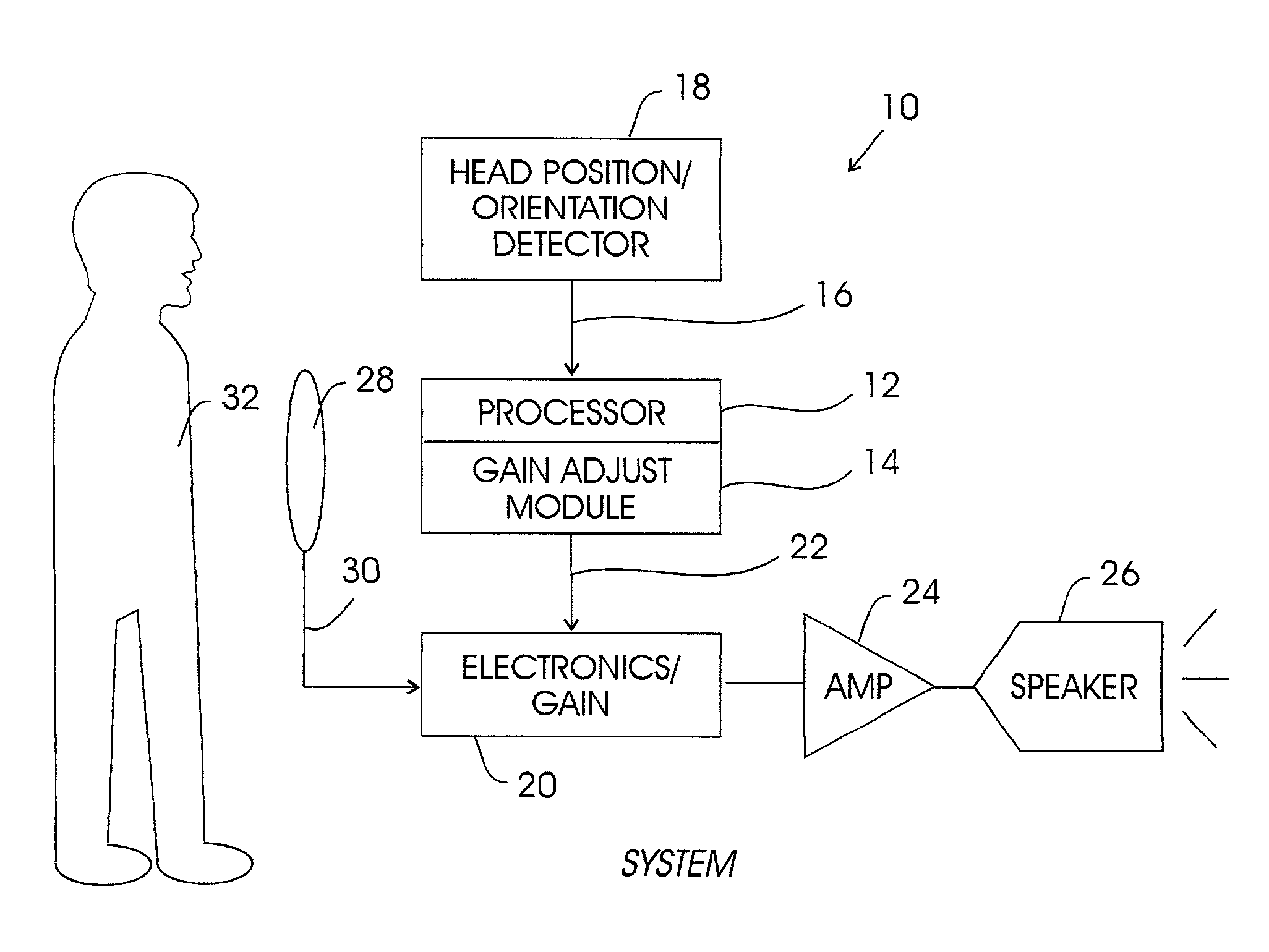
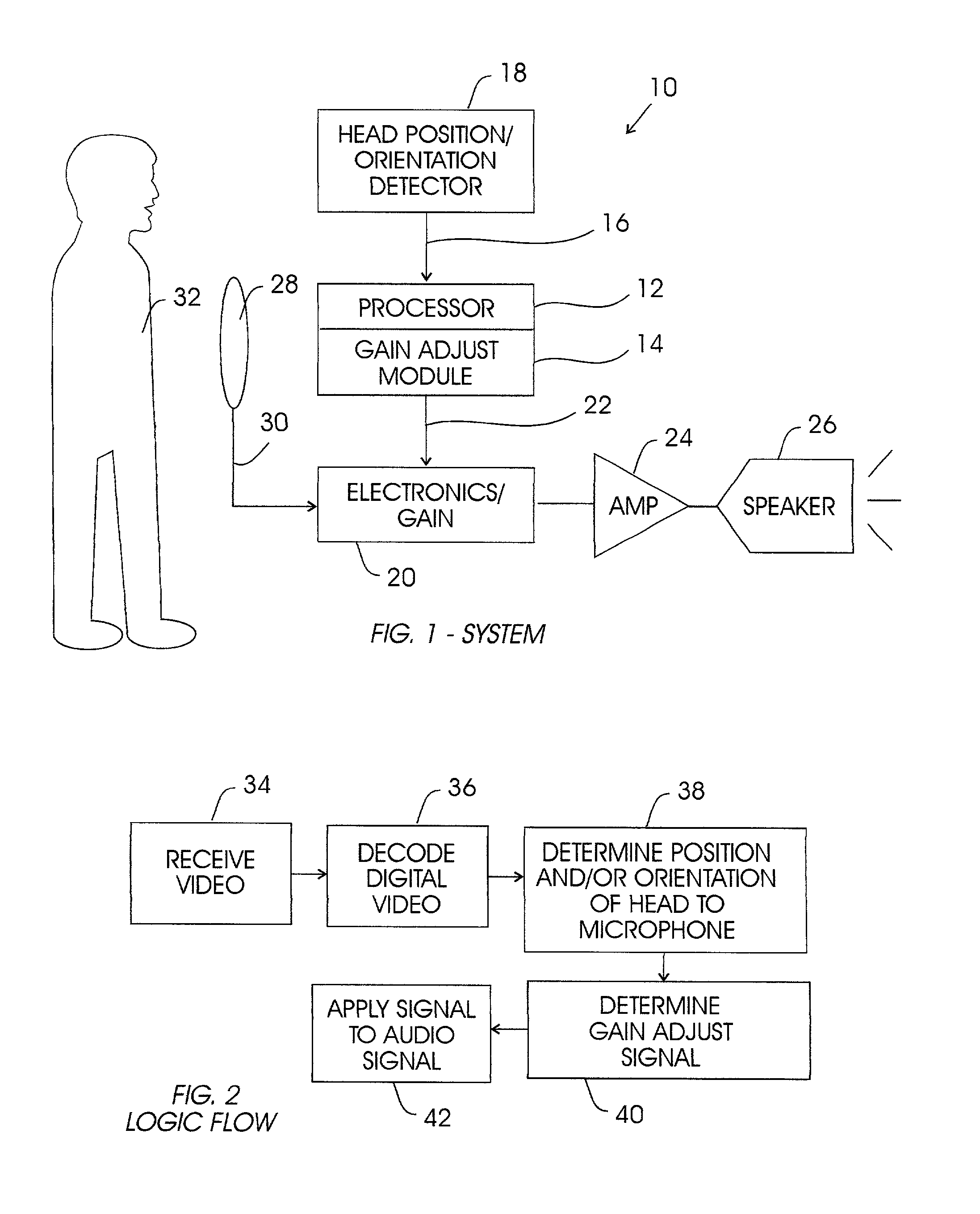
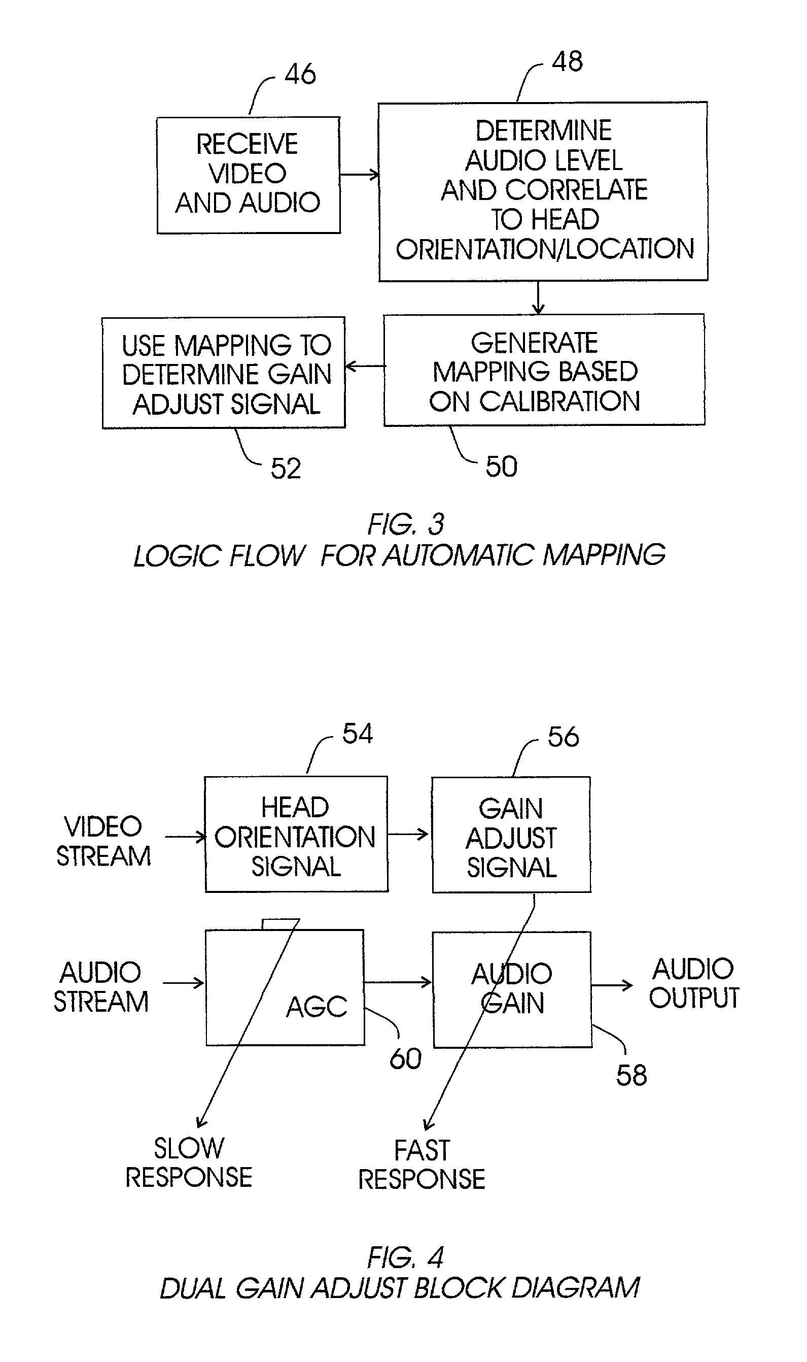
"The invention is a computer program that uses a person's position relative to a microphone to adjust the audio output from a digital processing apparatus. This can be done by receiving a video stream of the person and deriving the person's position from the video. The program can also use information from a motion or position sensing system, such as a video camera or a laser system, to determine the position. The program can adjust the audio gain based on the distance between the person's mouth and the microphone, or the orientation of the person's head. This allows for dynamic adjustment of the audio system based on the person's position. The invention can be implemented in a computer program or a computer system that includes an audio amplifier and a video camera. Overall, the invention provides a more precise and responsive audio output for video conferences and other situations where the person's position is not fixed."

Problems solved by technology

Should the speaker move away from the microphone or turn her head away from the 0° orientation, however, the sound level at the microphone is less than what the system was calibrated for.
The audio speaker volume accordingly decreases, which can be annoying and distracting.
On the other hand, if the system is calibrated for a head orientation of other than 0°, when the person subsequently speaks directly into the microphone the audio speaker volume increases, again potentially distracting the intended recipient or recipients from what the person is saying.
All of these approaches suffer drawbacks.
Unfortunately, a speaker might deliberately vary her voice volume, a speaking technique that is frustrated by systems that establish amplifier gain based only on received audio signals.

Method used


Image

  • System and method for microphone gain adjust based on speaker orientation
  • System and method for microphone gain adjust based on speaker orientation
  • System and method for microphone gain adjust based on speaker orientation

Examples


Embodiment Construction

[0020]Referring initially to FIG. 1, a system is shown, generally designated 10, which includes a digital processing apparatus, such as a computer or processor 12, which has a local or remote gain adjust module 14 that embodies the logic disclosed herein.

[0021]In one intended embodiment, the processor 12, may be a personal computer made by International Business Machines Corporation (IBM) of Armonk, N.Y., or it may be any computer, including computers sold under trademarks such as AS400, with accompanying IBM Network Stations. Or, the computer 12 may be a Unix computer, or IBM workstation, or an IBM laptop computer, or a mainframe computer, or any other suitable computing device, such as an ASIC chip.

[0022]The module 14 may be executed by a processor as a series of computer-executable instructions. These instructions may reside, for example, in RAM of the processor 12.

[0023]Alternatively, the instructions may be contained on a data storage device with a computer readable medium, suc...


PUM


Abstract

A system and method for automatically adjusting the gain of an audio system as a speaker's head moves relative to a microphone includes using a video of the speaker to determine an orientation of the speaker's head relative to the microphone and, hence, a gain adjust signal. The gain adjust signal is then applied to the audio system that is associated with the microphone to dynamically and continuously adjust the gain the audio system.

Description

BACKGROUND OF THE INVENTION[0001]1. Field of the Invention[0002]The present invention relates generally to adjusting the gain of one or more microphones based on the position and / or orientation of a speaker relative to the microphones.[0003]2. Description of the Related Art[0004]Audio systems, including stage systems, teleconferencing and video conferencing systems, lecture videotaping and distance learning systems, mobile telephones, and other media typically include one or more microphones for receiving a person's voice, an amplifier that amplifies the output of the microphone, and an audio speakers that plays the amplified sound. Ordinarily, when an audio system is calibrated, the volume output by the audio speaker is adjusted (by, e.g., adjusting the amplifier gain) to a desired volume for the case where a person speaks directly into the microphone. This can be thought of as calibrating the system for a 0° orientation of the person's head relative to the microphone, at a nominal...

Claims


Application Information

Patent Timeline
Patent Type & Authority Patents(United States)
IPC IPC(8): G06F17/00H04R3/00H04R29/00H04S1/00
CPCH04R3/00H04R29/004
Inventor AMIR, ARNONASHOUR, GAL
Owner LINKEDIN
Learn More