Connector

a technology of connecting rods and connectors, applied in the direction of coupling contact members, coupling device connections, coupling bases/cases, etc., can solve the problems of increasing increasing the cost, and increasing the number of assembling steps, so as to increase the cost, increase the number of parts, and the effect of severe dimensional precision

Inactive Publication Date: 2006-11-07
AUTONETWORKS TECH LTD +2
View PDF9 Cites 9 Cited by
  • Summary
  • Abstract
  • Description
  • Claims
  • Application Information

AI Technical Summary

Benefits of technology

[0007]To prevent the wear due to microseism between male and female terminals, it is necessary to eliminate the clearance in the lock portion of the male and female housings, the clearance between each terminal and the housing, and the clearance between outer faces of male and female housings in the state where the male and female connectors are fitted. However, to eliminate all those clearances, very severe dimensional precision and addition of securing member with another member such as screwing, pressing of spring member and special armoring member are required, causing various problems of an increased number of parts, an increased cost due to great increase in the number of assembling steps, lower workability, and restricted attachment space due to larger size of connector. Therefore, it was extremely difficult to take the measures for eliminating the above clearances.
[0010]With the first aspect of the invention, even if microseism occurs between the first terminal and the contact portion of the second terminal due to influence of vibration for the long term in the state where the first connector and the second connector are securely fitted, a gas tight face is left behind at the contact portion, because the slide distance is set within the range of contact area between the first terminal and the second terminal. Hence, the oxidation and abrasive wear are suppressed from occurring on this gas tight face, whereby the wear due to microseism between contact portions of the first and second terminals is remarkably decreased, and the connection reliability is maintained in the use for the long term.
[0012]With the second aspect of the invention, the emboss shape is formed according to the direction of microseism occurring between the first and second terminals, whereby the micro-seismic distance is easily set within the range of contact area.

Problems solved by technology

However, to eliminate all those clearances, very severe dimensional precision and addition of securing member with another member such as screwing, pressing of spring member and special armoring member are required, causing various problems of an increased number of parts, an increased cost due to great increase in the number of assembling steps, lower workability, and restricted attachment space due to larger size of connector.
Therefore, it was extremely difficult to take the measures for eliminating the above clearances.

Method used


Image

  • Connector
  • Connector
  • Connector

Examples


Embodiment Construction

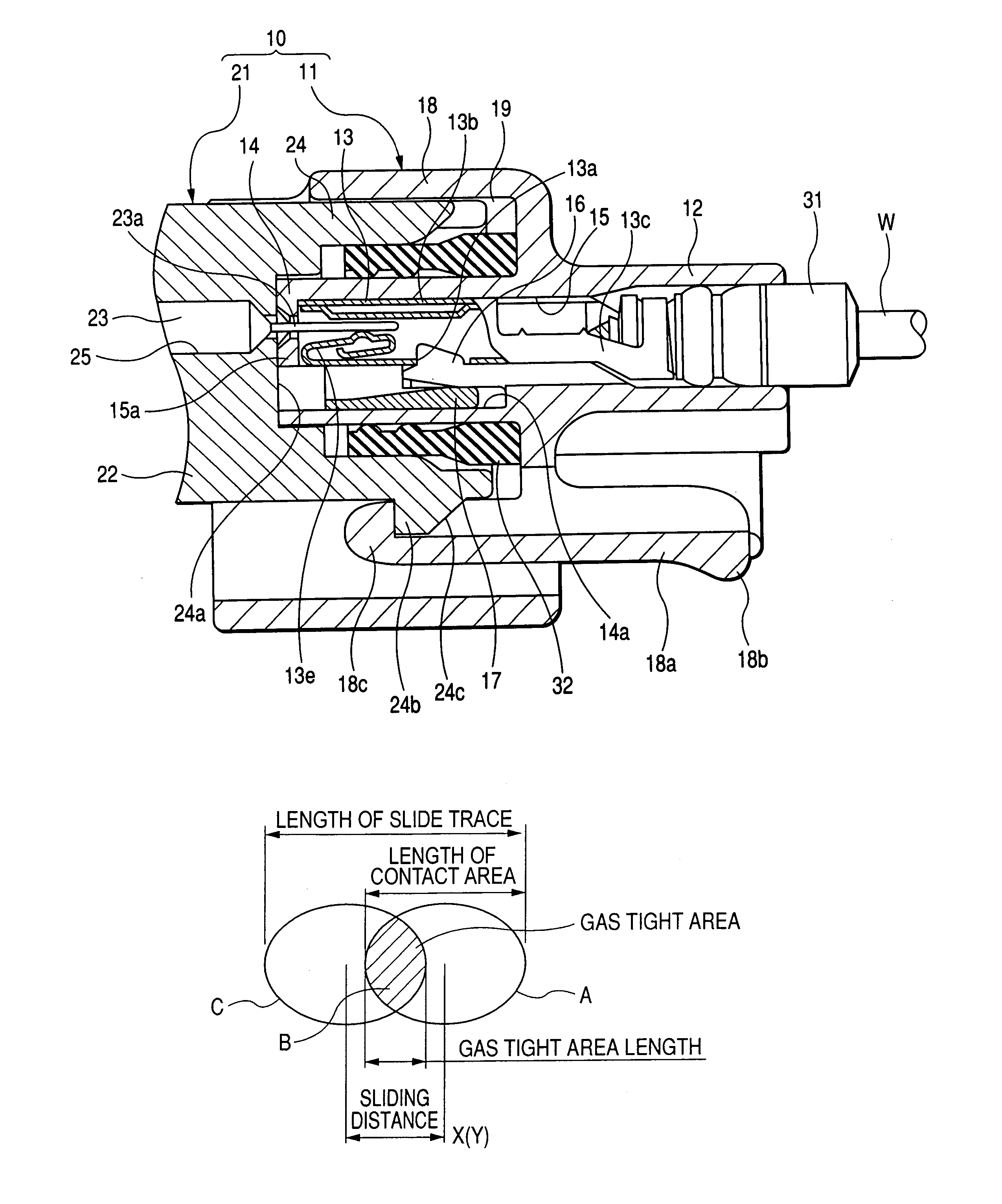
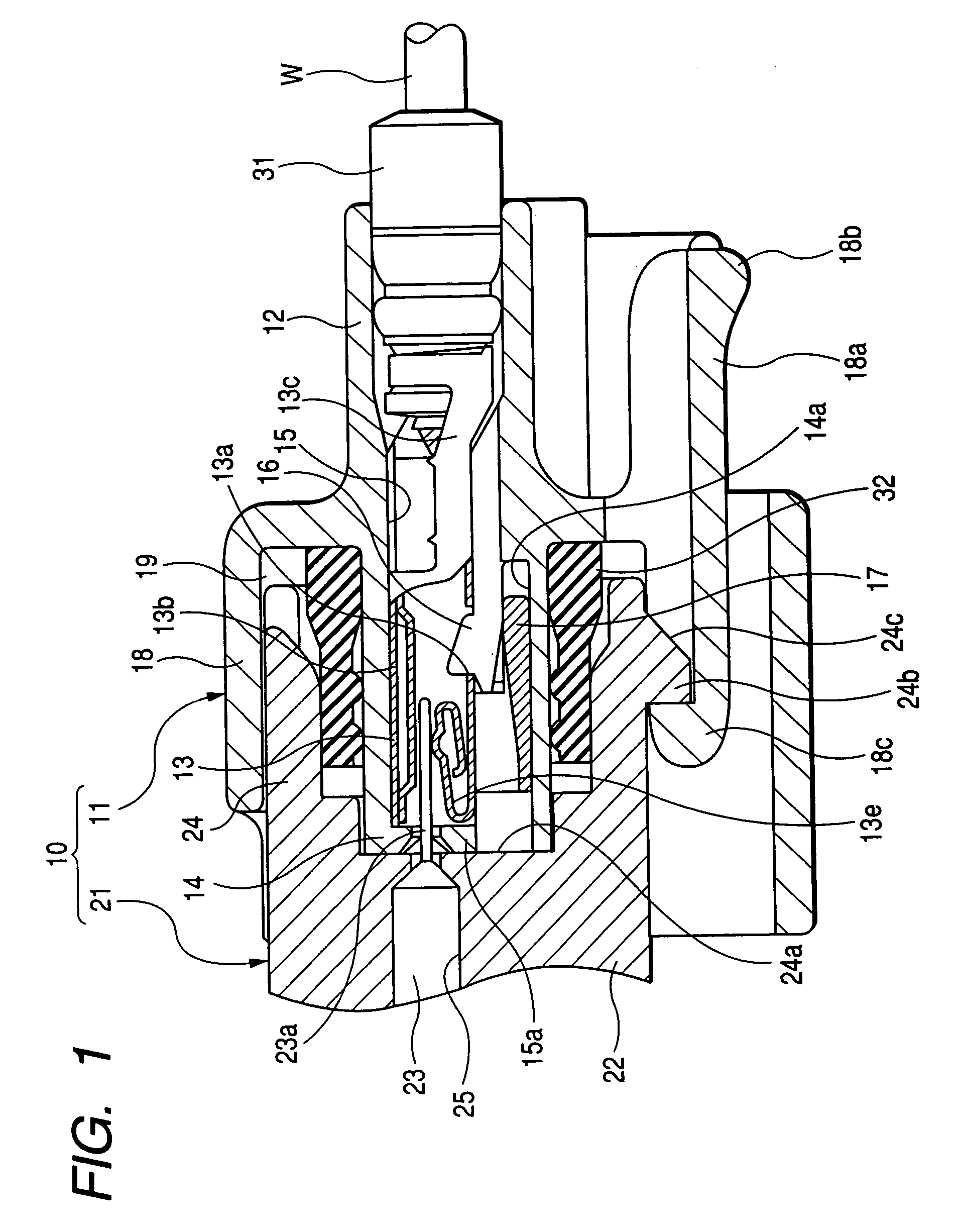
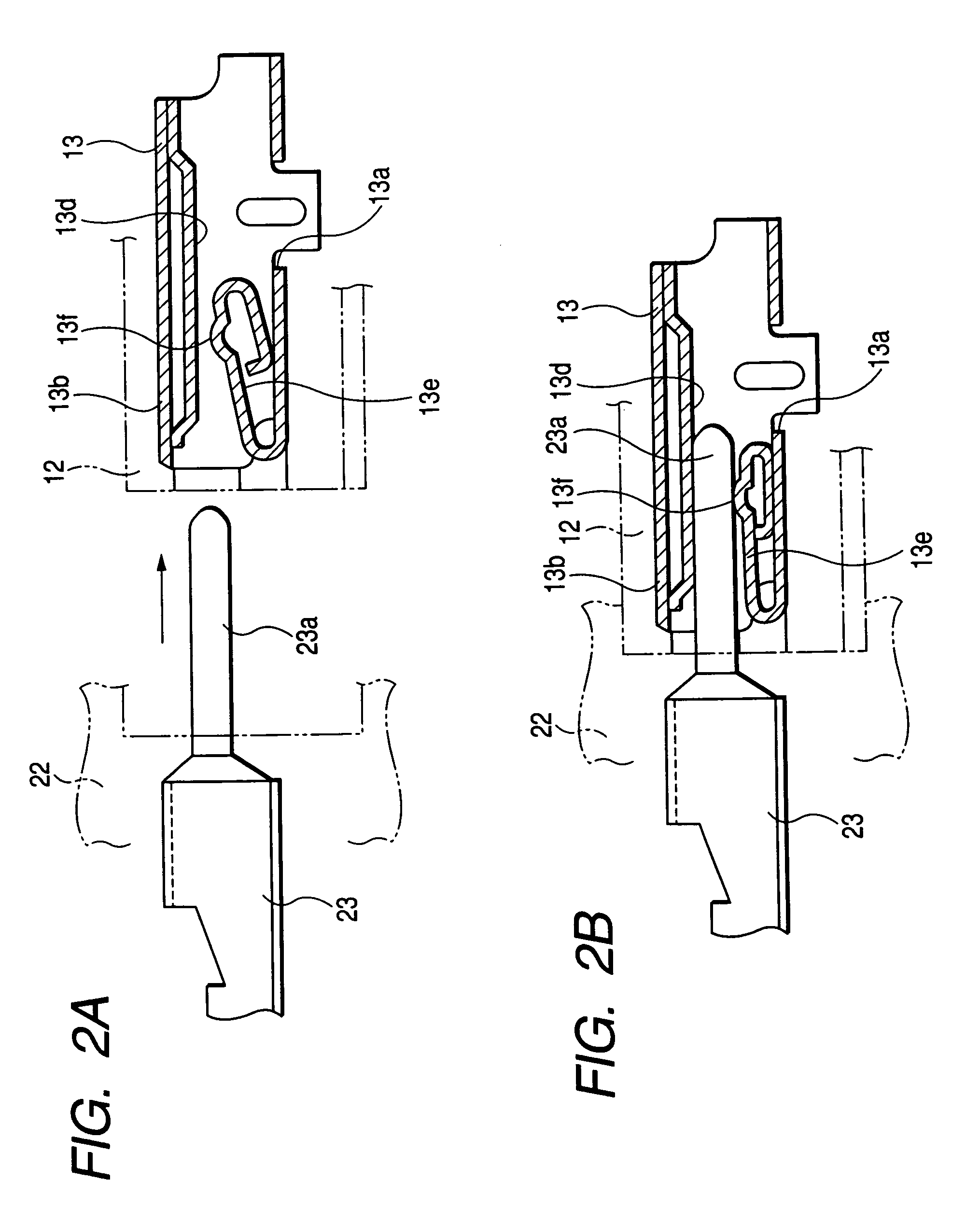
[0027]FIG. 1 shows the overall cross section of a connector according to an embodiment of the present invention, and FIGS. 2A and 2B show the detailed cross section of a terminal structure.

[0028]Hereinafter, the embodiment will be explained by referring a male or female type, but the present invention is not limited to the male or female connector.

[0029]This connector 10 is a water-proof type, and having a female connector 11 as a first connector and a male connector 21 as a second connector on the partner side, which are fitted together. The female connector 11 comprises a female housing 12 made of synthetic resin, and a female terminal 13 accommodated within the female housing 12, and the male connector 21 comprises a male housing 22 and a male terminal 23.

[0030]The female housing 12 is internally provided with a terminal receiving portion 14 fitted into a skirt portion 24 in the male housing 22, and the terminal receiving portion 14 is formed with a cavity 15 for receiving the fe...


PUM


Abstract

A connector has a first connector and a second connector in which a sliding distance between a first terminal and a second terminal is within a range of contact area in a contact portion between the first terminal and a contact portion of the second terminal in a state where the second connector and the first connector are securely fitted together by contacting the contact portion of the second terminal with the first terminal.

Description

BACKGROUND OF THE INVENTION[0001]1. Field of the Invention[0002]The present invention relates to a connector, and more particularly to a connector which prevents the connection reliability from being lower due to micro-seismic abrasion between the terminals under high vibration environments.[0003]2. Description of the Related Art[0004]Generally, when a wire harness for automobile is connected to another wire harness or the equipment apparatus provided in the automobile, a connector attached to a terminal of wire harness is fitted into a partner's connector. Usually, such a connection structure is one in which a female connector 1 having a female terminal 1a and a female housing 1b for accommodating this female terminal 1a and a male connector 2 having a male terminal 2a and a male housing 2b for accommodating this male terminal 2a are fitted together, as shown in FIG. 11 (refer to JP-A-8-236207). The female terminal 1a with the wire W crimped at the rear end is inserted into a cavit...

Claims


Application Information

Patent Timeline
Patent Type & Authority Patents(United States)
IPC IPC(8): H01R13/627H01R13/11H01R13/04H01R13/115H01R13/52H01R13/533
CPCH01R13/04H01R13/111H01R13/5221
Inventor SAITOH, YASUSHI
Owner AUTONETWORKS TECH LTD
Why Eureka
Try Eureka