Electrical connector

a technology of electrical connectors and connectors, applied in the direction of coupling device connections, connection contact member materials, coupling protective earth/shielding arrangements, etc., can solve the problems of high cost, difficulty in increasing the size of connectors, etc., and achieve the effect of reducing crosstalk in connectors

Active Publication Date: 2006-11-07
TYCO ELECTRONICS LOGISTICS AG (CH)
View PDF11 Cites 115 Cited by
  • Summary
  • Abstract
  • Description
  • Claims
  • Application Information

AI Technical Summary

Problems solved by technology

Improving connector performance and increasing contact density to increase signal carrying capacity without increasing the size of the connectors is challenging.
As would be expected, the higher performance connector also comes with a higher cost.

Method used


Image

  • Electrical connector
  • Electrical connector
  • Electrical connector

Examples


Embodiment Construction

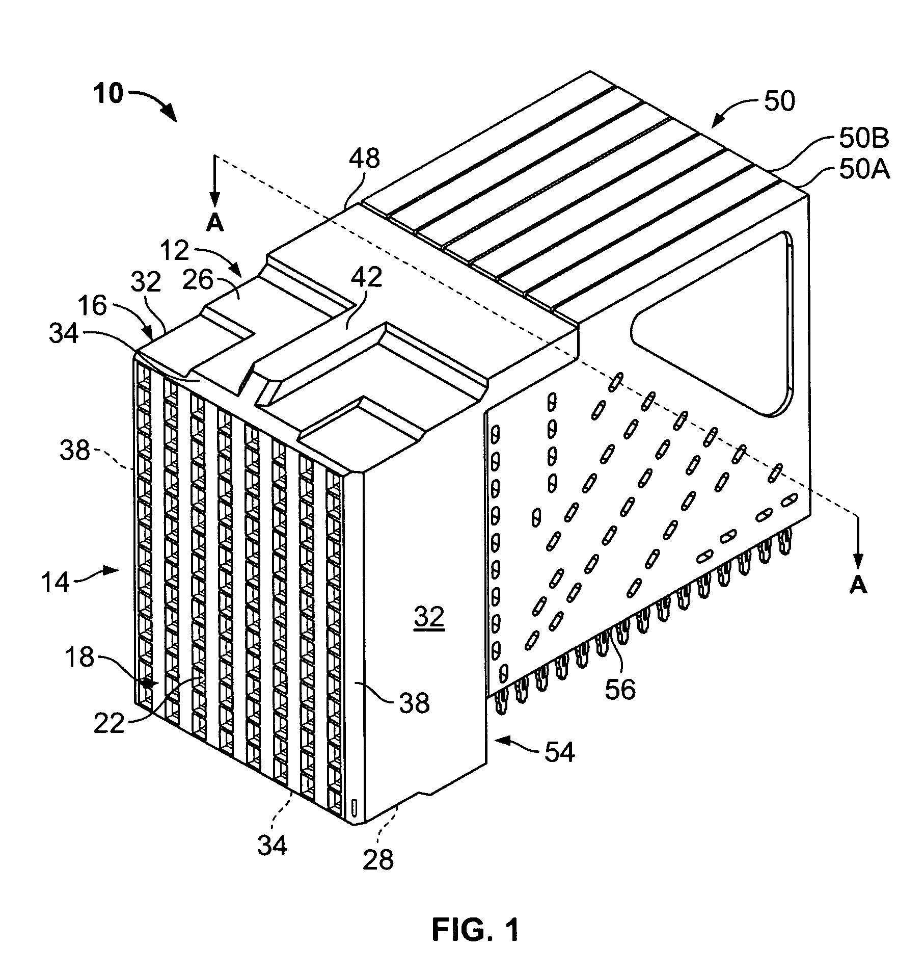
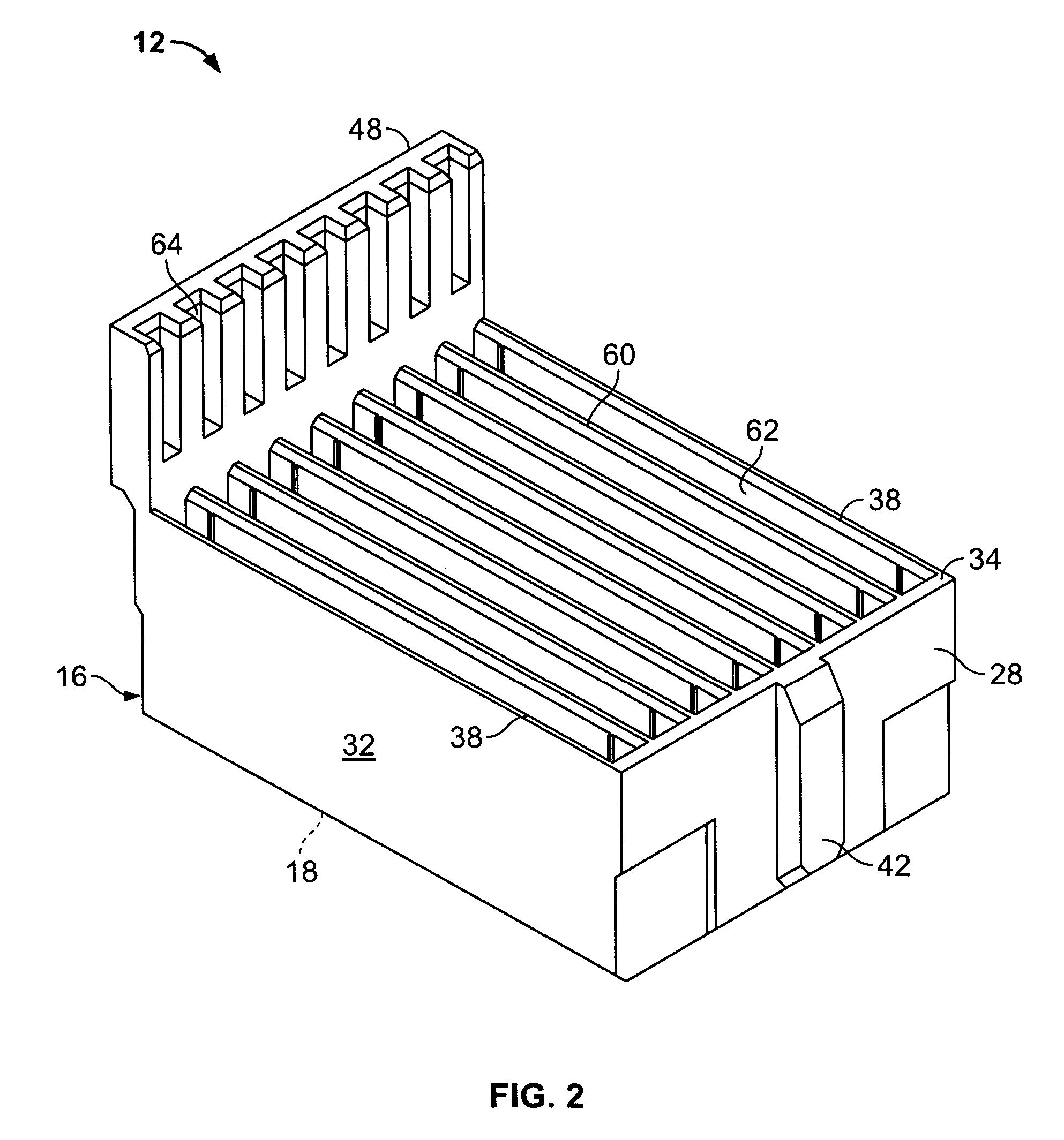
[0020]FIG. 1 illustrates an electrical connector 10 formed in accordance with an exemplary embodiment of the present invention. While the connector 10 will be described with particular reference to a receptacle connector, it is to be understood that the benefits herein described are also applicable to other connectors in alternative embodiments. The following description is therefore provided for purposes of illustration, rather than limitation, and is but one potential application of the inventive concepts herein.

[0021]The connector 10 includes a dielectric housing 12 having a forward mating end 14 that includes a shroud 16 and a mating face 18. The mating face 18 includes a plurality of contact cavities 22 that are configured to receive mating contacts (not shown) from a mating connector (not shown). The shroud 16 includes an upper surface 26 and a lower surface 28 between opposed sides 32. The upper and lower surfaces 26 and 28, respectively, each includes a chamfered forward edg...


PUM


Abstract

An electrical connector includes a housing and a plurality of contact modules in the housing. Each contact module includes a mating edge and a mounting edge. Each mating and mounting edge has a row of contacts including signal and ground contacts arranged in one of a first and second pattern. Adjacent contact modules in the housing have a different one of the first and second patterns. The first and second patterns each include pairs of signal contacts and individual ground contacts arranged in an alternating sequence. Each mating edge contact is electrically connected to a corresponding mounting edge contact by signal conductors and ground conductors extending along a predetermined path within the contact module. Each ground conductor has a width transverse to the predetermined path that is substantially equal to a combined transverse width across a pair of signal conductors in an adjacent contact module. The ground conductor shields the pair of signal conductors in the adjacent contact module.

Description

BACKGROUND OF THE INVENTION[0001]The invention relates generally to electrical connectors and, more particularly, to an electrical connector for transmitting signals in differential pairs.[0002]With the ongoing trend toward smaller, faster, and higher performance electrical components such as processors used in computers, routers, switches, etc., it has become increasingly important for the electrical interfaces along the electrical paths to also operate at higher frequencies and at higher densities with increased throughput.[0003]In a traditional approach for interconnecting circuit boards, one circuit board serves as a back plane and the other as a daughter board. The back plane typically has a connector, commonly referred to as a header, that includes a plurality of signal pins or contacts which connect to conductive traces on the back plane. The daughter board connector, commonly referred to as a receptacle, also includes a plurality of contacts or pins. Typically, the receptacl...

Claims


Application Information

Patent Timeline
Patent Type & Authority Patents(United States)
IPC IPC(8): H01R13/648H01R12/71
CPCH01R13/514H01R12/724H01R13/6471H01R13/6474H01R13/6585H01R13/65807
Inventor WHITEMAN, JR., ROBERT NEILDAVIS, WAYNE SAMUELGLOVER, DOUGLAS WADE
Owner TYCO ELECTRONICS LOGISTICS AG (CH)
Why Eureka
Try Eureka