Bone anchor implantation device

a bone anchor and implantation device technology, applied in the field of bone anchor implantation devices, can solve the problems of affecting the quality of life of women, the optimal handle position of conventional bone anchor devices is not always optimal for retrograde delivery, and the awkward fixed handle position of conventional bone anchor devices is particularly awkward when treating obese patients

Inactive Publication Date: 2006-11-07
BOSTON SCI SCIMED INC
View PDF242 Cites 43 Cited by
  • Summary
  • Abstract
  • Description
  • Claims
  • Application Information

AI Technical Summary

Benefits of technology

[0007]In another aspect, the invention provides a bone anchor implantation device with a handle that can be rotated relative to the longitudinal axis of the shaft during a bone anchor implantation procedure, to facilitate the insertion of the device into a body cavity and / or implantation of a bone anchor. For example, the device can be inserted into the vagina of a patient with the handle in one position, following which the handle can be rotated about the longitudinal axis of the device's shaft and locked into a second position, wherein the second position facilitates the application of a retrograde force or pulling action required for anchoring the bone anchor into a bone.
[0009]In one version of the device, the handle may be rotatable between two angular positions and may contain a stop assembly for locking the handle in a first or a second angular position. For example, a representative stop assembly has an outer cylinder, an inner cylinder and a spring. The outer cylinder is fixed to the handle and aligned with the shaft, and includes a circumferential slit having a pair of diametrically opposed detents, for example. The inner cylinder is rotatably disposed within the outer cylinder and is also fixed to the first end of the shaft. The inner cylinder includes a drive pin extending horizontally through the inner and outer cylinders. The drive pin has a pair of ends, one or both of which are received within the outer cylinder's circumferential slit and seatable within the detent(s). The seating of the drive pin within the detent(s) prevents rotation of the outer cylinder with respect to the inner cylinder. The spring is disposed within the outer cylinder and urges the inner cylinder in a direction toward the bone anchor-mount. Compression of the spring releases the drive-pin ends from the detents, permitting rotation of the handle.

Problems solved by technology

Female Stress Urinary Incontinence (FSUI) is a disorder that can interfere with daily activity and impair the quality of life of women.
However, the optimal configuration or position of the handle of such an instrument for insertion of the device into the vagina is not necessarily the optimal handle position for providing a retrograde force for implanting the bone anchors into the bone.
For example, the fixed handle position of conventional bone anchor devices is particularly awkward when treating obese patients.

Method used


Image

  • Bone anchor implantation device
  • Bone anchor implantation device
  • Bone anchor implantation device

Examples


Embodiment Construction

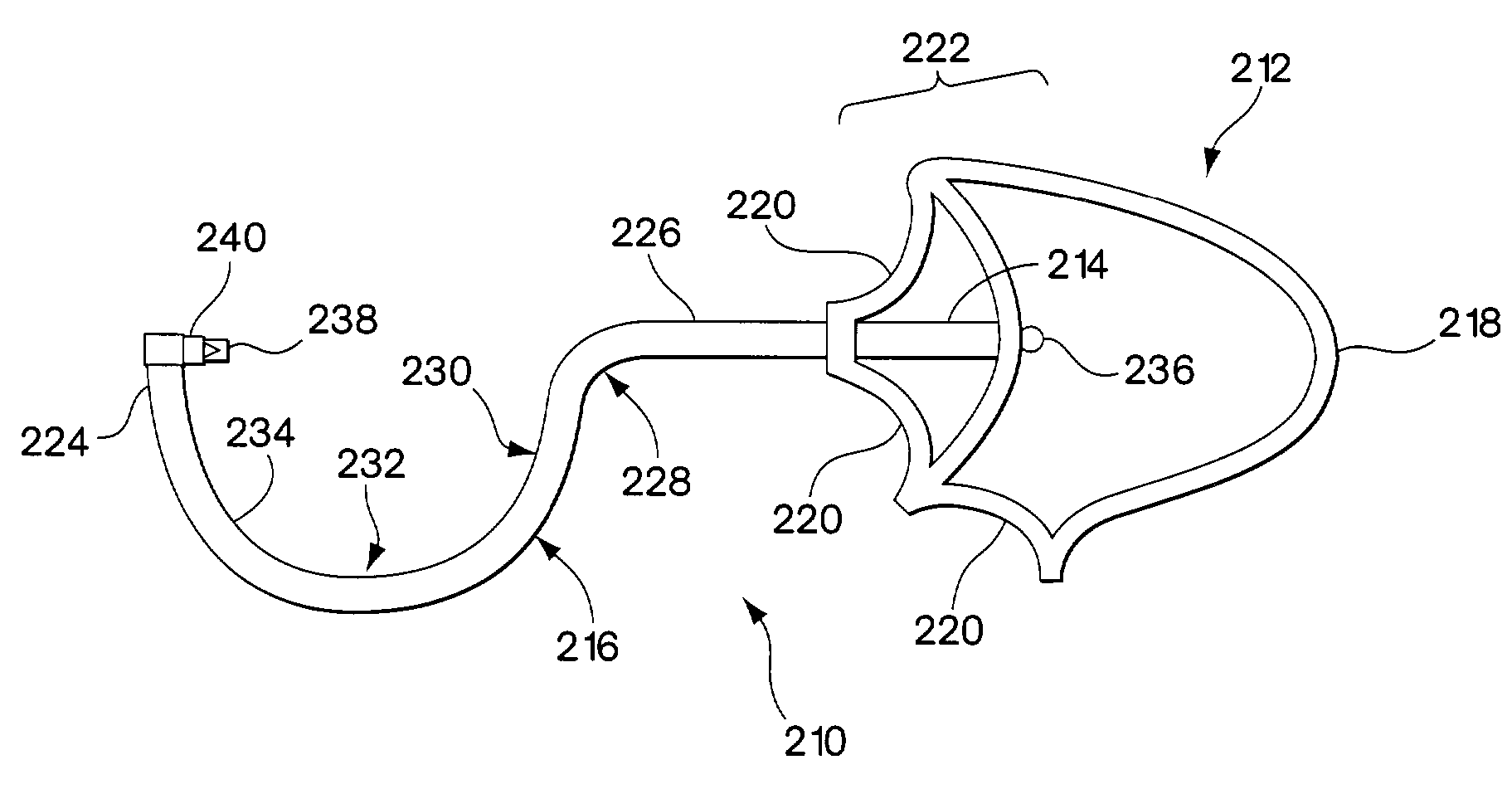
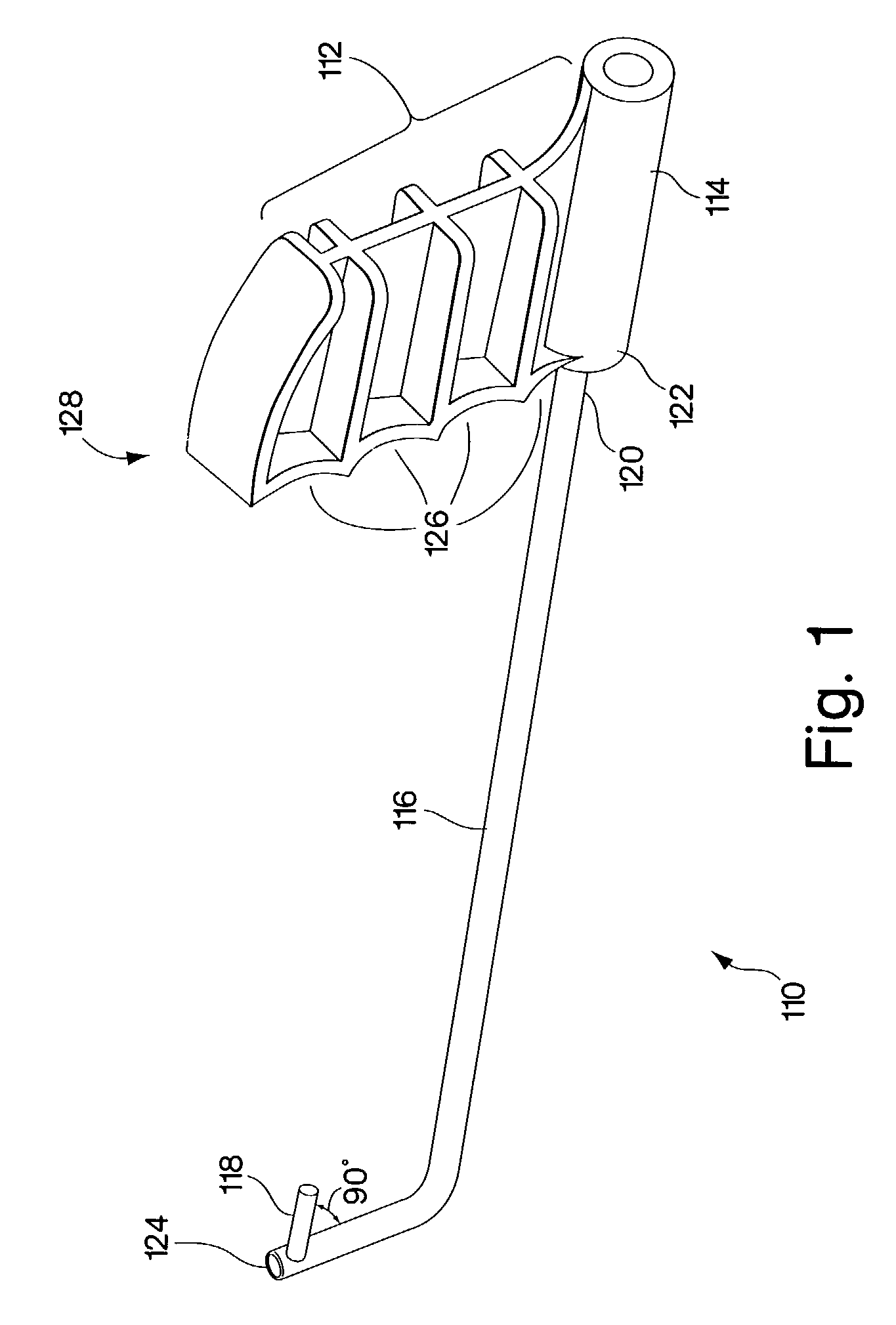
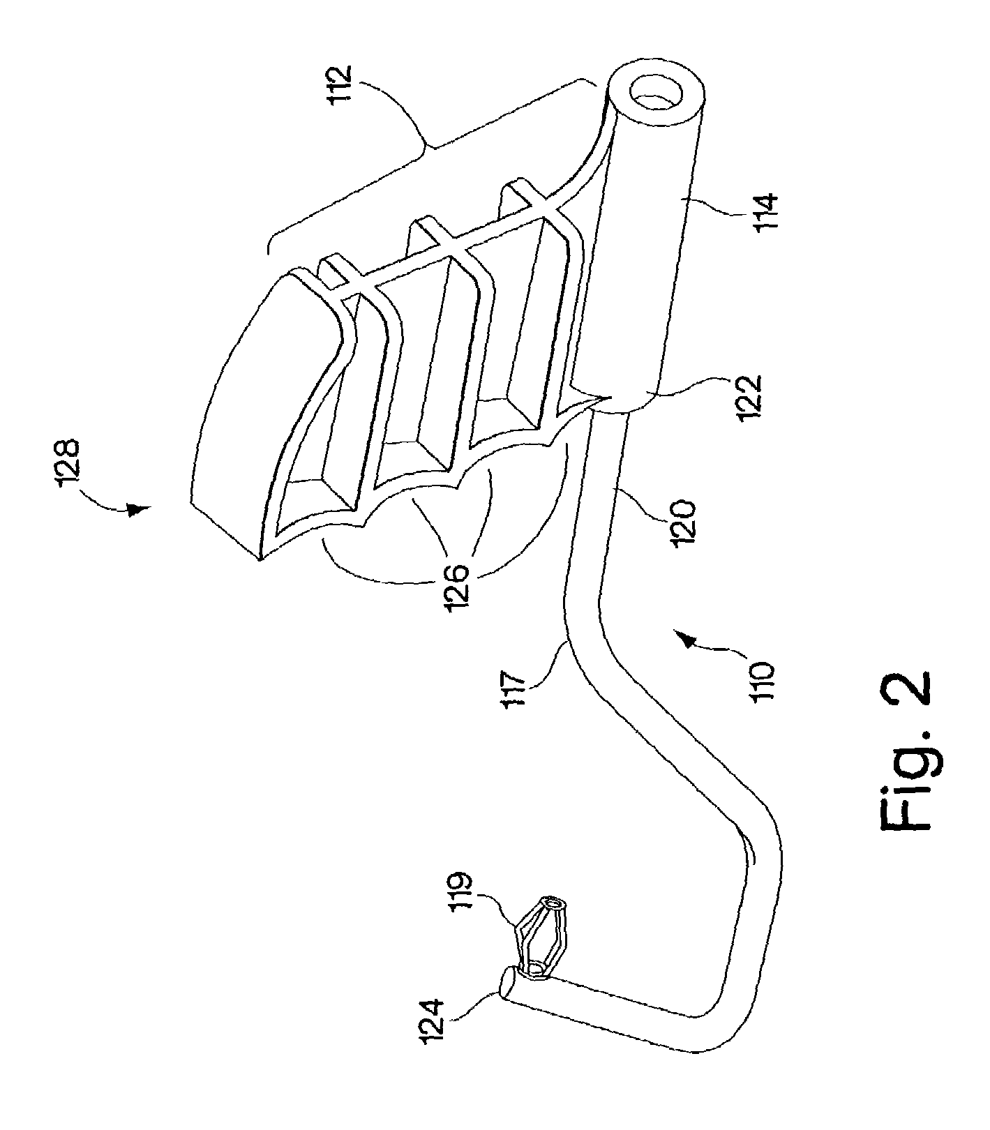
[0041]The present invention relates to a device for implanting a bone anchor into bone. It also relates to methods for improving or maintaining a patient's urinary continence in which bone anchors are inserted transvaginally into the posterior portion of the pubic bone or symphysis pubis.

[0042]A bone anchor implantation device in accordance with the invention may have an ergonomic handle which has at least one finger indentation in the distal end of the handle. The handle may have one, two, three or four or more finger indentations. In one version of this embodiment, the shaft may be attached to the handle between finger indentations.

[0043]A bone anchor implantation device in accordance with the invention may have a handle that can be rotated relative to the shaft of the device, facilitating bone anchor implantation by allowing a physician the flexibility of rotating the handle of the device during the procedure in order to optimize the angle of the bone anchor-mount and shaft relat...


PUM


Abstract

Bone anchor implantation devices and methods for their use are disclosed. The bone anchor implantation devices have an ergonometric and / or rotatable handle. The bone anchor implantation devices and methods find particular application for implanting a bone anchor for maintaining or improving urinary continence by suspending or stabilizing the bladder neck.

Description

TECHNICAL FIELD[0001]The invention relates to devices for manually implanting a bone anchor into bone.BACKGROUND OF THE INVENTION[0002]Female Stress Urinary Incontinence (FSUI) is a disorder that can interfere with daily activity and impair the quality of life of women. In approximately 30% of the women suffering from FSUI, incontinence is caused by intrinsic sphincter deficiency (ISD), a condition in which the valves of the urinary sphincter do not properly coapt. In approximately another 30% of FSUI sufferers, incontinence is caused by hypermobility, a condition in which the muscles around the bladder relax, causing the bladder neck and proximal urethra to rotate and descend in response to increases in intraabdominal pressure. Hypermobility may be the result of pregnancy or other conditions which weaken the muscles. Urinary incontinence may also be caused by a combination of ISD and hypermobility. Other causes of urinary incontinence include birth defects, disease, injury, aging, ...

Claims


Application Information

Patent Timeline
Patent Type & Authority Patents(United States)
IPC IPC(8): A61B17/56A61B17/00A61B17/04
CPCA61B17/0401A61B2017/00424A61B2017/0046A61B2017/00805A61B2017/0409
Inventor HOFFMAN, KEITH
Owner BOSTON SCI SCIMED INC
Why Eureka
Try Eureka