Electric fan for vehicle use

a technology for electric fans and vehicles, applied in the direction of positive displacement liquid engines, piston pumps, liquid fuel engines, etc., can solve the problems that water and dust flowing into the device together with cooling air cannot be sufficiently separated, and achieve the effect of reducing the sectional area of the passage, and reducing the sectional area

Active Publication Date: 2006-11-07
DENSO CORP +1
View PDF10 Cites 23 Cited by
  • Summary
  • Abstract
  • Description
  • Claims
  • Application Information

AI Technical Summary

Benefits of technology

[0022]Therefore, compared with the structure described in the above patent document in which the labyrinth structure is composed in a space inside the motor, the labyrinth structure can be formed in a remarkably large space. For the above reasons, when the passage length of the labyrinth structure is extended without especially reducing the sectional area of the passage of the labyrinth structure, water and dust contained in cooling air can be effectively separated and removed from the cooling air on the inlet side of the cooling air introducing port (24).
[0023]As it is unnecessary to especially reduce the sectional area of the passage in the labyrinth structure, the ventilating resistance of the labyrinth structure can be reduced to a relatively low value. As a result, it becomes possible to make the action of separating water and dust from the cooling air compatible with maintaining a volume of the cooling air of cooling the motor.
[0026]Due to the foregoing, water and dust, which are separated in the space inside a waterproof cover (25), can be smoothly discharged onto the inlet side of the air introducing passage 26 by an inclined face of a bent portion (25d) directed obliquely downward.
[0028]Due to the foregoing, in addition to water and dust on the bent portion (25d), water and dust on the second wall face (21e) can be also easily discharged by the inclined face directed downward.
[0030]According to the investigation made by the present inventors, the following was confirmed. When the overlapping length (L5) is set at 3 mm or more, water and dust can be effectively separated from cooling air by the action of the labyrinth structure.

Problems solved by technology

Therefore, water and dust flowing into the device together with cooling air cannot be sufficiently separated.
As a result, the following problems may be encountered.

Method used


Image

  • Electric fan for vehicle use
  • Electric fan for vehicle use
  • Electric fan for vehicle use

Examples


Embodiment Construction

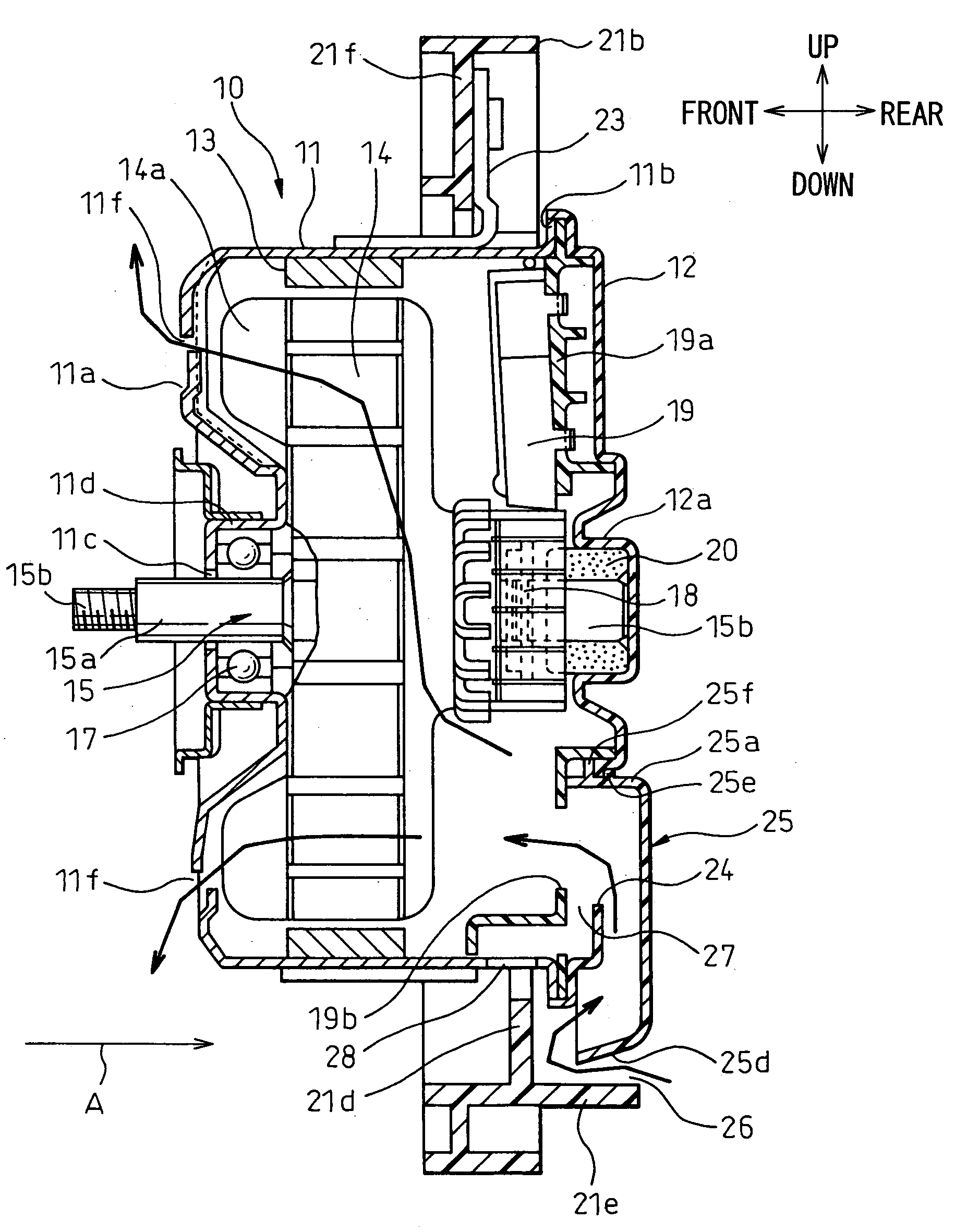
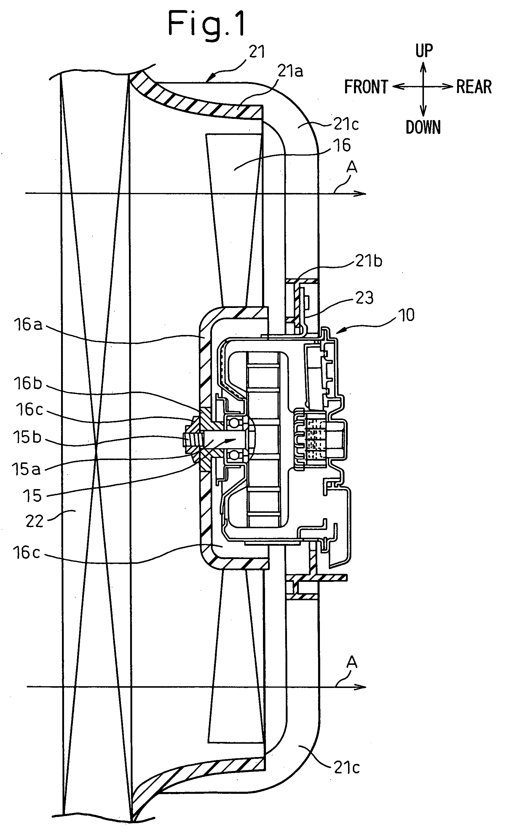
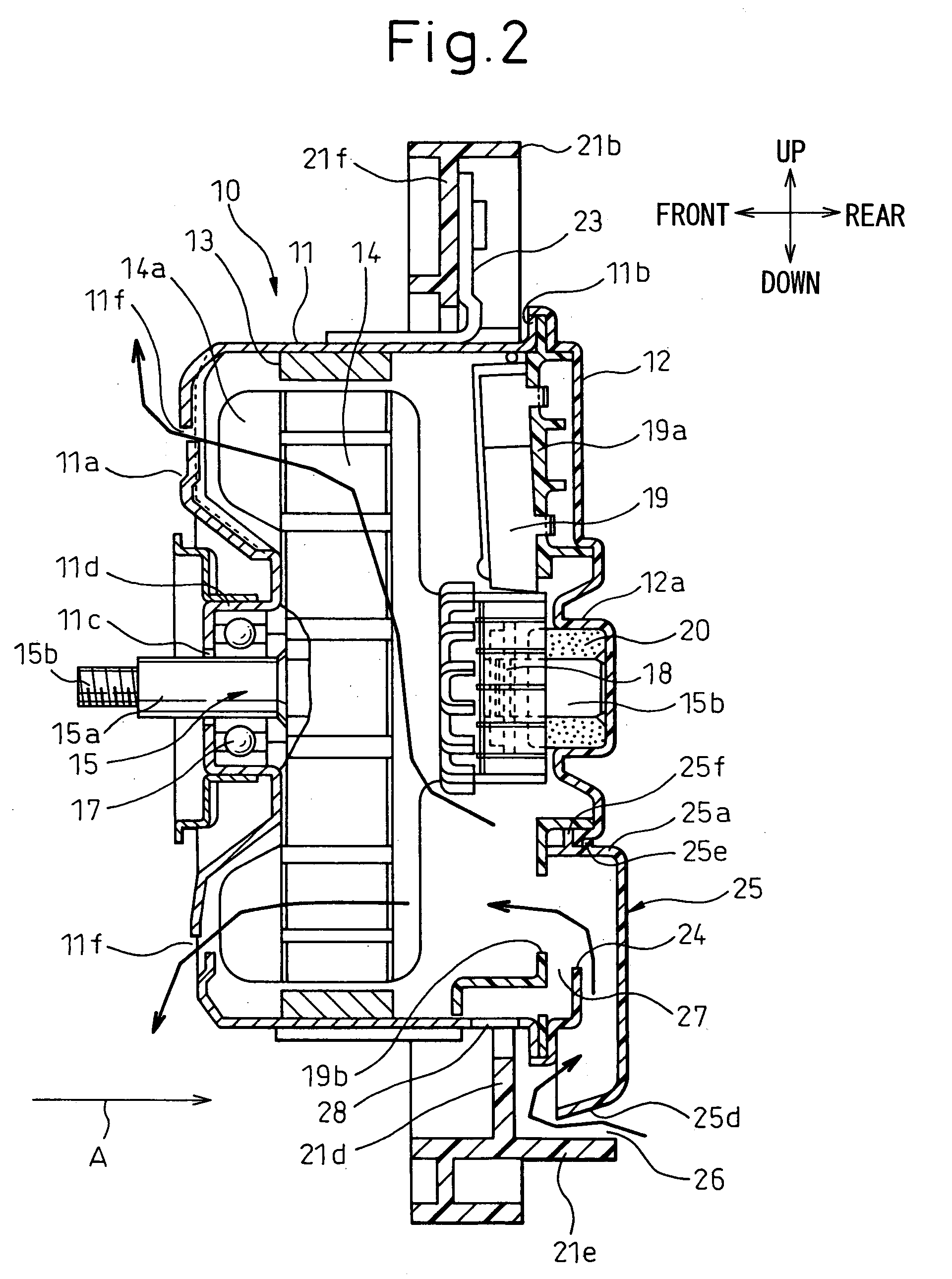
[0046]First of all, a first embodiment of the present invention will be explained below. FIGS. 1 to 4 are views showing the first embodiment of the present invention. FIG. 1 is a sectional view showing an entire arrangement of the electric fan device for vehicle use of the first embodiment of the present invention, FIG. 2 is an enlarged sectional view of the motor portion of FIG. 1, FIG. 3 is a right side view of FIG. 2, and FIG. 4 is an enlarged view showing a primary portion of FIG. 2. In this connection, the arrows of up, down, front and rear in the drawings indicate the directions in the case where the electric fan for vehicle use of the invention is mounted on a vehicle.

[0047]In FIGS. 1 and 2, the motor 10 for driving a fan is mounted on a vehicle so that the axial direction of the fan can be directed in the longitudinal direction (the horizontal direction) of the vehicle. The motor 10 for driving a fan includes a cylindrical body housing 11 made of iron which is generally refe...


PUM


Abstract

The cooling air introducing port 24 is open to a lower portion of an axial direction end portion of the motor housing member 11, 12, the water-proof cover 25 for covering the cooling air introducing port 24 is attached to the outside of the axial direction end portion of the housing member 11, 12, and the air introducing passage 26 having a labyrinth structure is composed of the bent portion 25d provided in a lower end portion of the water-proof cover 25, the first wall face 21d provided in the annular portion 21b of the shroud and the second wall face 21e.

Description

BACKGROUND OF THE INVENTION[0001]1. Field of the Invention[0002]The present invention relates to an electric fan used for moving air to a radiator of a vehicle. More particularly, the present invention relates to a structure for introducing cooling air into a motor for driving a fan.[0003]2. Description of the Related Art[0004]Concerning the device for introducing cooling air into a motor of an electric fan for vehicle use, the device described in the official gazette of JP-A-9-74718 is well-known.[0005]According to the above patent document, cooling air introducing port, which is directed downward, is formed in an end portion of an end housing of a motor used for driving a fan. Further, first to the third labyrinth plates are provided in a passage from this cooling air introducing port to the inside of the motor.[0006]The first labyrinth plate is contacted with and fixed to a cylindrical main body housing of the motor and directed in the direction substantially perpendicular to the...

Claims


Application Information

Patent Timeline
Patent Type & Authority Patents(United States)
IPC IPC(8): H02K5/10H02K5/12H02K9/00
CPCH02K5/10F04D25/082H02K5/20H02K5/207F04D29/5806H02K9/26
Inventor TAKEUCHI, KAZUHIROODA, SHINICHIKUMAKI, KENJITANINO, TOSHIHIROSUZUKI, SHINYA
Owner DENSO CORP
Why Eureka
Try Eureka