
Digital camera for image device calibration

Inactive Publication Date: 2006-11-07
HEWLETT PACKARD DEV CO LP
View PDF10 Cites 21 Cited by
  • Summary
  • Abstract
  • Description
  • Claims
  • Application Information

AI Technical Summary

Problems solved by technology

Such devices have typically been costly and relegated to manufacturing and other test facilities when the cost is justified.
However, consumer and small scale usage has not been adequately addressed.
This has become a problem with the ever increasing usage of images and graphics in which image fidelity is increasingly important.
However, this method is subjective and requires substantial user effort and experimentation.

Method used


Image

  • Digital camera for image device calibration
  • Digital camera for image device calibration
  • Digital camera for image device calibration

Examples


Embodiment Construction

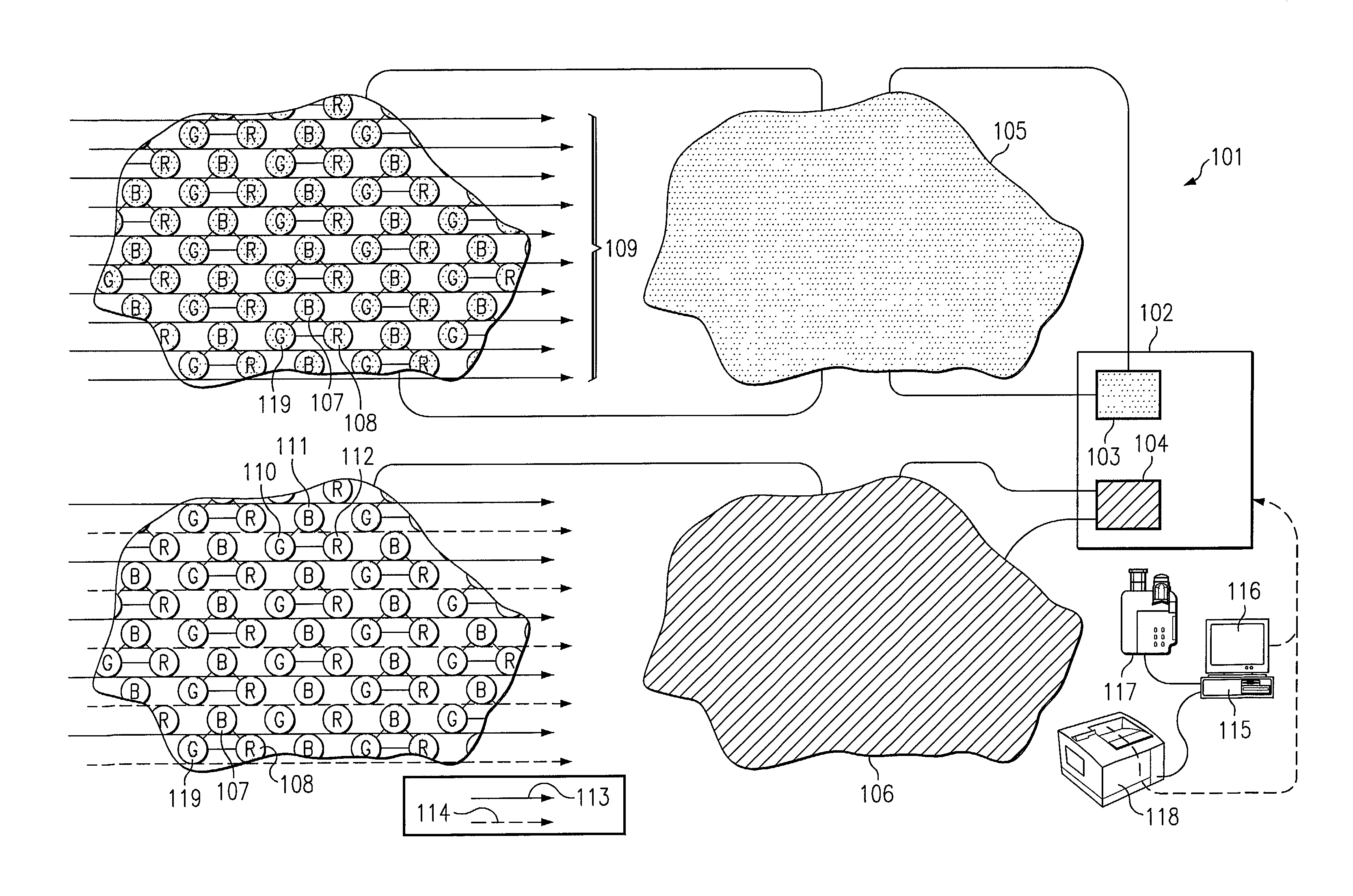
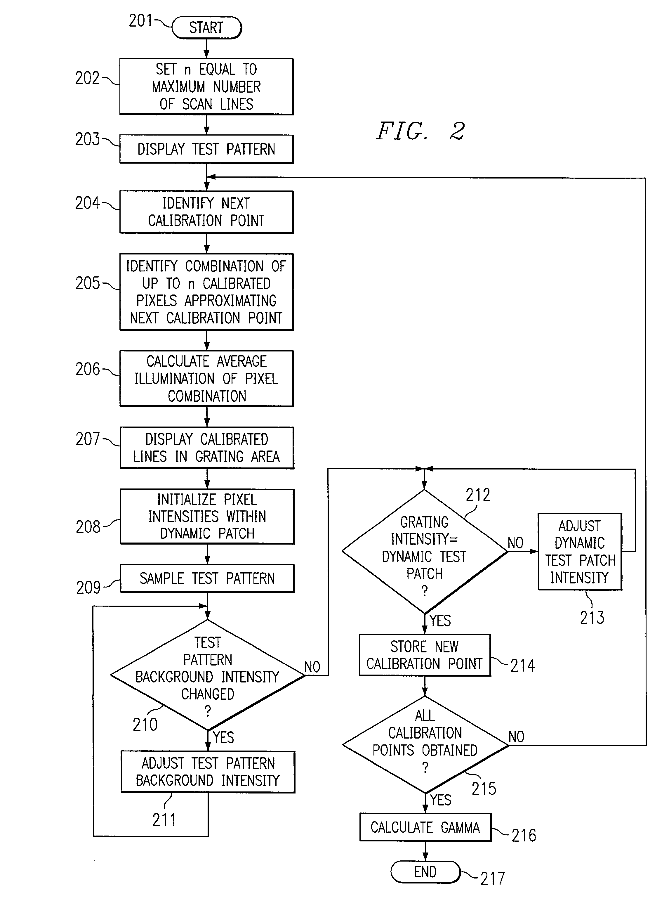
[0010]The invention provides an improved apparatus for a method of analyzing the output of a display device or printer to correct for non-linearities. For example, the invention employs a conventional imaging device such as a video camera together with a calibration grating displayed on a monitor or printed by a printer to create a closed loop control of a dynamic test patch area. The intensity of the dynamic test patch area is adjusted by varying the appropriate control parameters until the color specific light intensity from the patch is equal to the standardized grating area. Repeating this process to obtain multiple points, the invention may be used to map the true output from the device being calibrated to the corresponding input parameters used to provide that output. A correction may then be formulated, preferably in the form of a “gamma” correction. Gamma correction and gamma functions are described in, for example, U.S. Pat. No. 5,812,286 of Lynn issued Sep. 22, 1998 and en...


PUM


Abstract

The invention is directed to an apparatus for calibrating an output of an image output device, comprising an image input device configured to image an output of the image output device; and a test pattern generator having an output of a dynamic test patch area and a grating area connected to an input of the image output device and responsive to the image input device for adjusting an intensity level of the dynamic test patch area to match an average intensity level of the grating area.

Description

TECHNICAL FIELD[0001]The present invention relates to calibration of output devices and specifically calibrating printers and display devices using a digital camera.BACKGROUND[0002]Continuing advances in computers and digital communications have resulted in the proliferation of digital imagery, such images including, for example, still images, full motion video, graphics incorporated into on-line catalogs, advertisements and web pages. While substantial effort has been expended to ensure that data storage and transmission provides an accurate representation of the original data, fidelity of a rendered image with respect to the original or a desired image has been largely left to the individual user.[0003]Prior techniques to ensure the fidelity of an output device such as a video monitor or color printer accurately represents a desired image relied heavily upon specialized devices such as CRT color analyzers, such as the Minolta CA-100 or the Sencore CPT 288 color analyzer. These dev...

Claims


Application Information

Patent Timeline
IPC IPC(8): G06F3/12G06F15/00G06K1/00H04N17/04
CPCH04N17/04
Inventor SILVERSTEIN, D. AMNON
Owner HEWLETT PACKARD DEV CO LP
Learn More