
Magnetic recording head with heating device

a heating device and recording head technology, applied in the direction of metal sheet core head, mounting head within the housing, instruments, etc., can solve the problems of limited conventional reduction, low recording density, and inability to include both features in the head (e.g., in a single magnetic recording head). achieve the effect of increasing the recording density

Inactive Publication Date: 2006-11-07
WESTERN DIGITAL TECH INC
View PDF9 Cites 63 Cited by
  • Summary
  • Abstract
  • Description
  • Claims
  • Application Information

AI Technical Summary

Benefits of technology

[0005]It is therefore an object of the present invention to provide a heating device and a magnetic head which includes the heating device, which combines the advantages of thermally-induced protrusion and thermally-assisted recording.
[0007]In addition, a fly height between said recording head and said recording medium is reduced by an amount corresponding to said thermal protrusion.
[0013]Further, the thermal protrusion may increase the thermal conductance between the recording head and a magnetic disk. In addition, the thermal protrusion may occur at the write gap.
[0016]The present invention also includes a method of magnetic recording which includes heating a portion of a magnetic head so as to both induce a thermal protrusion in the recording head and enhance a thermal conductance between the recording head and a recording medium.
[0018]The present invention thus provides a heating device and a magnetic recording head which combines the advantages of both thermally-induced protrusion and thermally-assisted recording. This allows the present invention to further increase the recording density over conventional devices and methods.

Problems solved by technology

One of the challenges to improve the storage densities further involves the reduction of the fly height.
A further reduction with conventional means is limited, at least partly, by the smoothness of the air bearing and magnetic recording disk surfaces.
Although the advantages of thermally-induced protrusion (U.S. Pat. No. 5,991,113) as well as thermally-assisted recording (U.S. Pat. Nos. 6,233,206 and 6,493,183) have been recognized separately, no conventional device has been able to include both features in a head (e.g., in a single magnetic recording head).
Therefore, none of the conventional devices have been able to realize the benefits of both TIP and TAR in a single magnetic recording head.

Method used


Image

  • Magnetic recording head with heating device
  • Magnetic recording head with heating device
  • Magnetic recording head with heating device

Examples


Embodiment Construction

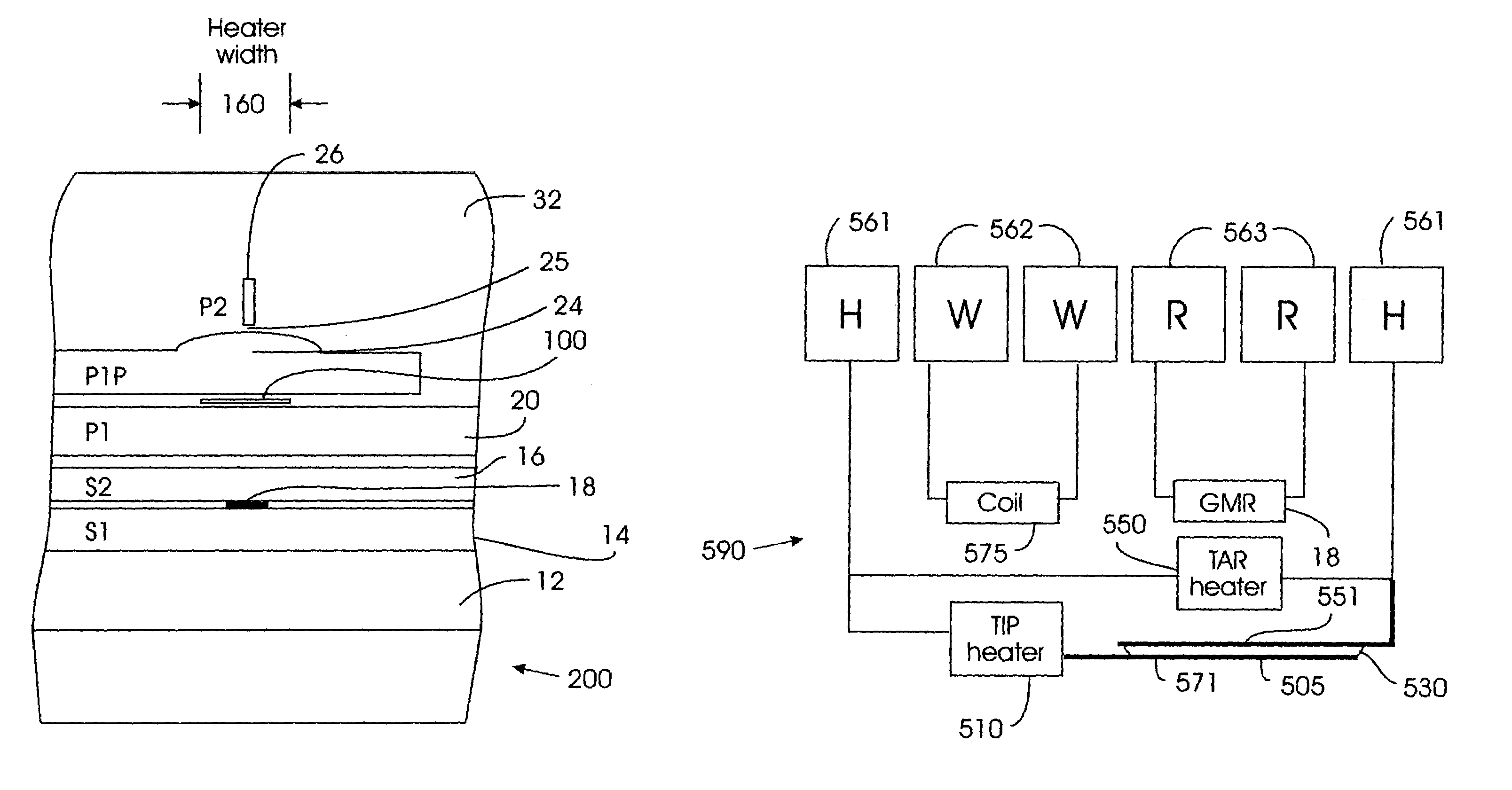
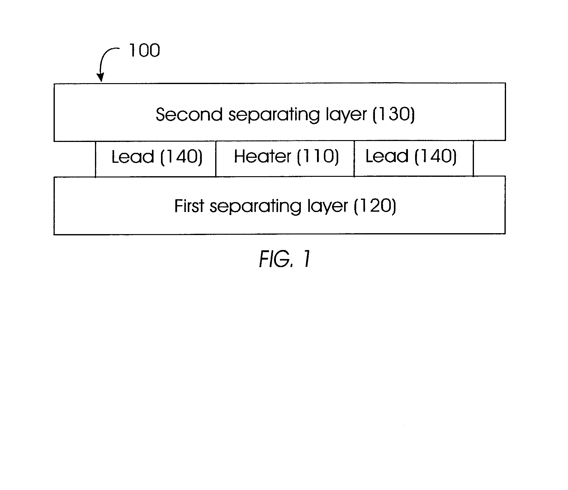
[0032]Referring to FIG. 1, the present invention includes a heating device 100 for a magnetic recording head. A dimension (e.g., a length in a down-track direction) of the heating device 100 is selected to induce a thermal protrusion in the recording head (and thereby lower the fly height of the recording head), and to increase the temperature in the recording medium (thereby reducing the coercivity of the medium). The thermally-induced protrusion increases the thermal conductance between the recording head and the recording medium. In other words, the heating device 100 may be used for both thermally-induced protrusion and thermally-assisted recording in a magnetic head.

[0033]For purposes of this application, the term “width” will refer to a dimension in an across track direction, the term “height” will refer to a dimension in a direction away from the air bearing surface (ABS) of the magnetic head, and the term “thickness” will refer to a dimension in a down-track direction.

[0034]...


PUM

PropertyMeasurementUnit
temperatureaaaaaaaaaa
widthaaaaaaaaaa
fly heightsaaaaaaaaaa

Abstract

A magnetic recording disk drive has a magnetic recording head that includes first and second separating layers, and a heater formed between the first and second separating layers. The heater has a dimension such a thermal protrusion is induced in the recording head and a thermal conductance between the recording head and a recording medium is enhanced.

Description

BACKGROUND OF THE INVENTION[0001]The present invention relates generally to a magnetic recording head and more particularly to a magnetic recording head that includes a heating device for thermally-induced protrusion (TIP) of the head and thermally-assisted recording (TAR) on a magnetic recording medium.[0002]In recent years storage densities of hard drives have been increasing at a tremendous pace. One of the challenges to improve the storage densities further involves the reduction of the fly height. In magnetic storage a recording head flies via an air-bearing surface over a spinning disk. Current products have fly heights of less than 10 nm. A further reduction with conventional means is limited, at least partly, by the smoothness of the air bearing and magnetic recording disk surfaces.[0003]A solution to this problem is to exploit the thermally-induced protrusion of a part of the recording head. Another possible improvement in storage densities can be achieved by local heating ...

Claims


Application Information

Patent Timeline
Patent Type & Authority Patents(United States)
IPC IPC(8): G11B5/147G11B21/02G11B5/02G11B5/00G11B5/10G11B5/105G11B5/127G11B5/31G11B5/39G11B5/54G11B5/58
CPCG11B5/10G11B5/105G11B5/127G11B5/3136G11B5/54G11B5/58G11B5/6064G11B5/3103G11B5/3967G11B2005/001G11B2005/0021
Inventor HAMANN, HENDRIK F.POON, CHIE CHINGSALO, MICHAEL P.WICKRAMASINGHE, HEMANTHA KUMAR
Owner WESTERN DIGITAL TECH INC
Learn More